Datasheet 187
Functional Description
Once these registers are locked down, they become Read-Only registers and any
software writes to these registers will have no effect. To unlock the registers, the GPIO
Lockdown Enable (GLE) bit is required to be cleared to ‘0’. When the GLE bit changes
from a ‘1’ to a ‘0’ a System Management Interrupt (SMI#) is generated if enabled.
Once the GPIO_UNLOCK_SMI bit is set, it can not be changed until a PLTRST# occurs.
This ensures that only BIOS can change the GPIO configuration. If the GLE bit is
cleared by unauthorized software, BIOS will set the GLE bit again when the SMI# is
triggered and these registers will continue to be locked down.
5.15.5 Serial POST Codes over GPIO
The PCH adds the extended capability allowing system software to serialize POST or
other messages on GPIO. This capability negates the requirement for dedicated
diagnostic LEDs on the platform. Additionally, based on the newer BTX form factors, the
PCI bus as a target for POST codes is increasingly difficult to support as the total
number of PCI devices supported are decreasing.
5.15.5.1 Theory of Operation
For the PCH generation POST code serialization logic will be shared with GPIO. These
GPIOs will likely be shared with LED control offered by the Super I/O (SIO) component.
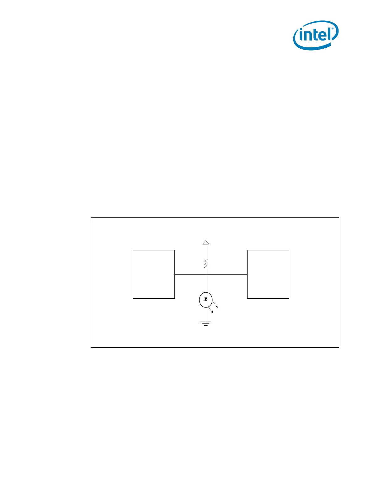
Figure 5-7 shows a likely configuration.
The anticipated usage model is that either the PCH or the SIO can drive a pin low to
turn off an LED. In the case of the power LED, the SIO would normally leave its
corresponding pin in a high-Z state to allow the LED to turn on. In this state, the PCH
can blink the LED by driving its corresponding pin low and subsequently tri-stating the
buffer. The I/O buffer should not drive a ‘1’ when configured for this functionality and
should be capable of sinking 24 mA of current.
An external optical sensing device can detect the on/off state of the LED. By externally
post-processing the information from the optical device, the serial bit stream can be
recovered. The hardware will supply a ‘sync’ byte before the actual data transmission
to allow external detection of the transmit frequency. The frequency of transmission
should be limited to 1 transition every 1 s to ensure the detector can reliably sample
Figure 5-7. Serial Post over GPIO Reference Circuit
SIO
V_3P3_STBY
LED
R
Note: The pull-up value is based on the brightness required.
PCH
 Loading...
