Datasheet 57
Signal Description
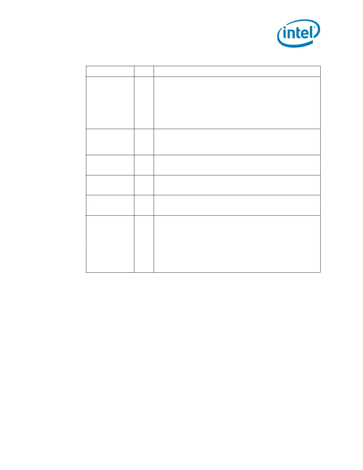
GNT0# (not
available in
mobile)
GNT1#/ GPIO51
GNT2#/ GPIO53
GNT3#/ GPIO55
O
PCI Grants: GNT functionality is Reserved.
GNT[3:1]# pins can instead be used as GPIO.
Pull-up resistors are not required on these signals. If pull-ups are
used, they should be tied to the Vcc3_3 power rail.
NOTES:
1. GNT[3:1]#/GPIO[55,53,51] are sampled as a functional
strap. See Section 2.27 for details.
2. GNT[3:0]# functionality is not available.
CLKIN_PCILOO
PBACK
I
PCI Clock: This is a 33 MHz clock feedback input to reduce skew
between PCH PCI clock and clock observed by connected PCI
devices. This signal must be connected to one of the pins in the
group CLKOUT_PCI[4:0]
PCIRST# (not
available in
mobile)
O PCI Reset: Reserved.
PLOCK# (not
available in
mobile)
I/O PCI Lock: Reserved.
SERR# (not
available in
mobile)
I/OD System Error: Reserved.
PME# I/OD
PCI Power Management Event: PCI peripherals drive PME# to
wake the system from low-power states S1–S5. PME# assertion can
also be enabled to generate an SCI from the S0 state. In some
cases the PCH may drive PME# active due to an internal wake
event. The PCH will not drive PME# high, but it will be pulled up to
VccSus3_3 by an internal pull-up resistor.
Can be used with PCI legacy mode on platforms using a PCIe-to-PCI
bridge. Downstream PCI devices would need to have PME# routed
from the connector to the PCH PME# pin.
Table 2-3. PCI Interface Signals (Sheet 2 of 2)
Name Type Description
 Loading...
