Datasheet 679
EHCI Controller Registers (D29:F0, D26:F0)
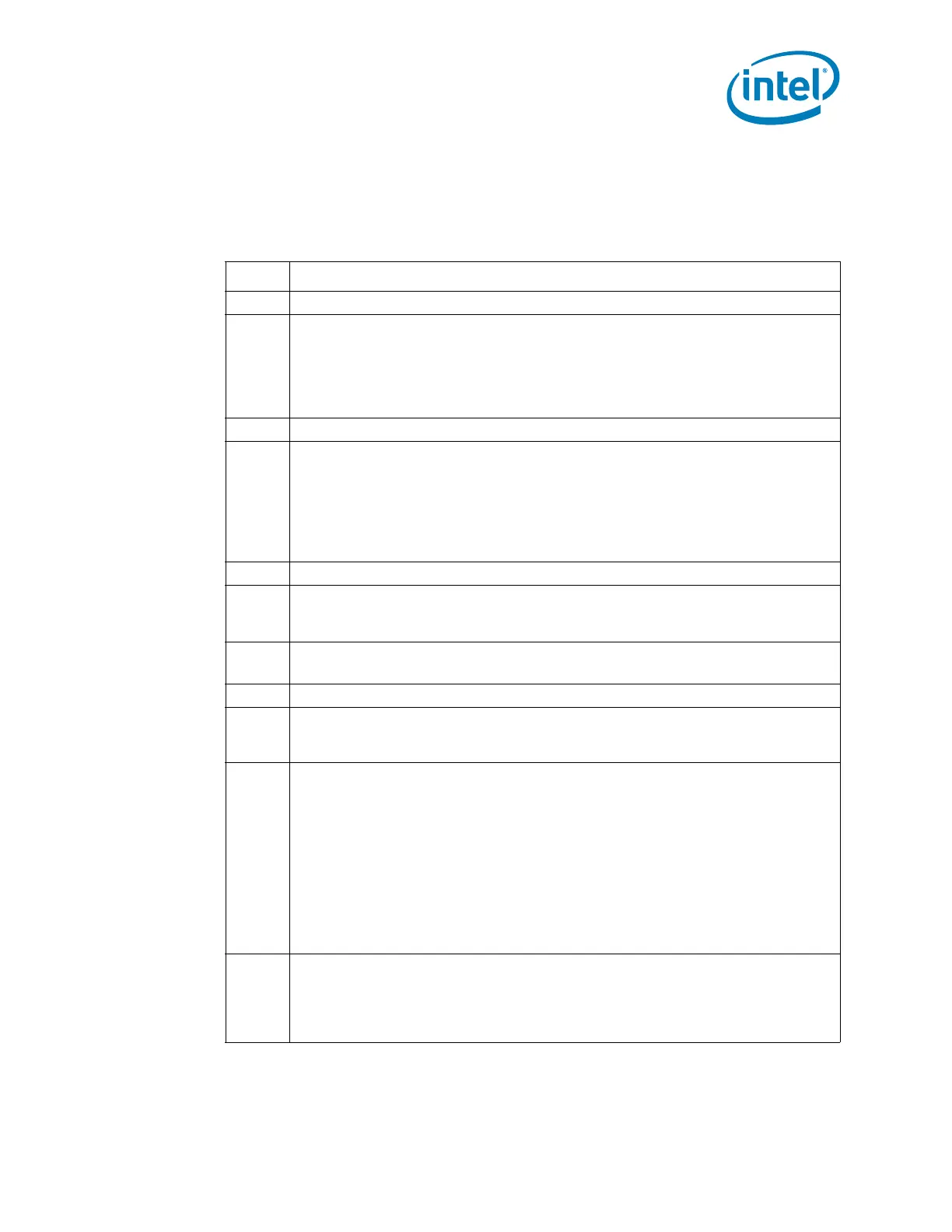
16.2.3.1 CNTL_STS—Control/Status Register
Offset: MEM_BASE + A0h Attribute: R/W, R/WC, RO
Default Value: 00000000h Size: 32 bits
Bit Description
31 Reserved
30
OWNER_CNT — R/W.
0 = Ownership of the debug port is NOT forced to the EHCI controller (Default)
1 = Ownership of the debug port is forced to the EHCI controller (that is, immediately
taken away from the companion Classic USB Host controller) If the port was
already owned by the EHCI controller, then setting this bit has no effect. This bit
overrides all of the ownership-related bits in the standard EHCI registers.
29 Reserved
28
ENABLED_CNT — R/W.
0 = Software can clear this by writing a 0 to it. The hardware clears this bit for the
same conditions where the Port Enable/Disable Change bit (in the PORTSC
register) is set. (Default)
1 = Debug port is enabled for operation. Software can directly set this bit if the port is
already enabled in the associated PORTSC register (this is enforced by the
hardware).
27:17 Reserved
16
DONE_STS — R/WC. Software can clear this by writing a 1 to it.
0 = Request Not complete
1 = Set by hardware to indicate that the request is complete.
15:12
LINK_ID_STS — RO. This field identifies the link interface.
0h = Hardwired. Indicates that it is a USB Debug Port.
11 Reserved.
10
IN_USE_CNT — R/W. Set by software to indicate that the port is in use. Cleared by
software to indicate that the port is free and may be used by other software. This bit
is cleared after reset. (This bit has no affect on hardware.)
9:7
EXCEPTION_STS — RO. This field indicates the exception when the
ERROR_GOOD#_STS bit is set. This field should be ignored if the
ERROR_GOOD#_STS bit is 0.
000 =No Error. (Default)
Note: This should not be seen since this field should only be checked if there is
an error.
001 =Transaction error: Indicates the USB 2.0 transaction had an error (CRC, bad
PID, timeout, etc.)
010 =Hardware error. Request was attempted (or in progress) when port was
suspended or reset.
All Other combinations are reserved
6
ERROR_GOOD#_STS — RO.
0 = Hardware clears this bit to 0 after the proper completion of a read or write.
(Default)
1 = Error has occurred. Details on the nature of the error are provided in the
Exception field.
 Loading...