PCH Pin States
94 Datasheet
NOTES:
1. Simulation data shows that these resistor values can range from 10 k to 40 k.
2. Simulation data shows that these resistor values can range from 9 k to 50 k.
3. Simulation data shows that these resistor values can range from 15 k to 40 k.
4. Simulation data shows that these resistor values can range from 7.5 k to 16 k.
5. Simulation data shows that these resistor values can range from 14.25 k to 24.8 k.
6. Simulation data shows that these resistor values can range from 10 k to 30 k.
7. The pull-up or pull-down on this signal is only enabled at boot/reset for strapping function.
8. Simulation data shows that these resistor values can range from 10 k to 20 k. The
internal pull-up is only enabled during PLTRST# assertion.
9. The pull-down on this signal is only enabled when in S3.
10. The pull-up or pull-down on this signal is only enabled during reset.
11. The pull-up on this signal is not enabled when PCIRST# is high.
12. The pull-up on this signal is not enabled when PWROK is low.
13. Simulation data shows that these resistor values can range from 15 k to 31 k.
14. The pull-down is disabled after pins are driven strongly to logic zero when PWROK is
asserted.
15. The pull-up or pull-down is not active when PLTRST# is NOT asserted.
16. The pull-down is enabled when PWROK is low.
17. External termination is also required on these signals for JTAG enabling.
18. External termination is also required on these signals for JTAG enabling.
19. Pull-down is enabled only when PCIRST# pin is driven low.
20. Pull-up is disabled after RSMRST# is deasserted.
21. The Controller Link Clock and Data buffers use internal pull-up or pull-down resistors to
drive a logical 1 or 0.
22. Pull-up is enabled only in Deep S4/S5 state.
23. Pull-down is enabled only in Deep S4/S5 state.
24. When the interface is in BUS IDLE, the Internal Pull-down of 10 k is enabled. In normal
transmission, a 400 pull-down takes effect, the signal will be override to logic 1 with
pull-up resistor (37 ) to VCC 1.5 V.
25. This is a 350- normal pull-down, signal will be overridden to logic 1 with pull-up resistor
(31 ) to VCC 1.05 V.
26. Internal pull-down serves as Rx termination and is enabled after PLTRST# deasserts.
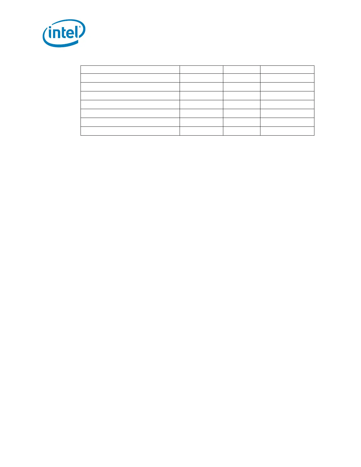
SATA[3:2]GP/GPIO[37:36] Pull-down 20K 3, 15
ACPRESENT/GPIO31 Pull-down 20K 23
PCIECLKRQ5#/GPIO44 Pull-up 20K 1, 20
PCIECLKRQ7#/GPIO46 Pull-up 20K 1, 20
SATA1GP/GPIO19 Pull-up 20K 3
SUSACK# Pull-up TBD
PECI Pull-down 0.35k 25
Table 3-1. Integrated Pull-Up and Pull-Down Resistors (Sheet 2 of 2)
Signal Resistor Type Nominal Notes
 Loading...
