3.14 KP (Keep)
■
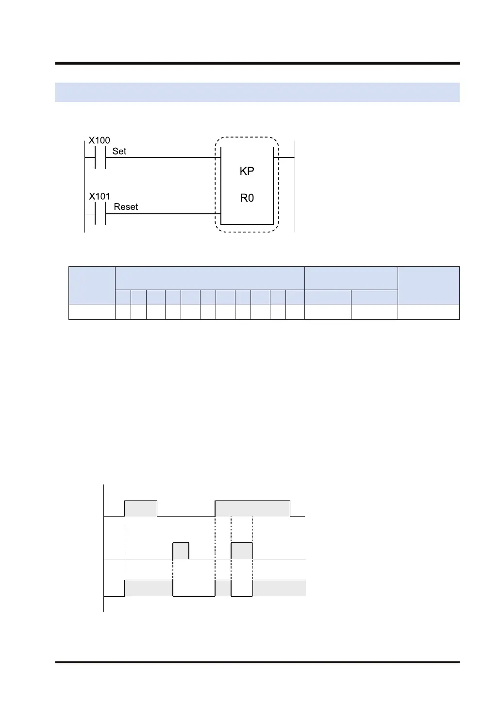
Ladder diagram
■
Devices that can be specified (indicated by ●)
Operand
Bit device
Specification of bit of
word device
Index modifier
X Y R L T C P E SR IN OT DT.n LD.n
bit ● ● ● ● ● ● ● ● ●
■
Outline of operation
● This instruction turns ON the specified coil output when the set input (X100) turns ON and
holds the ON state. Release the output state when the reset input (X101) turns ON.
● While the state is being held, the output state is held regardless of the ON or OFF state of
the set input (X100) until the reset input (X101) is entered.
● If the set input (X100) and the reset input (X101) turn ON simultaneously, the reset input
(X101) will take precedence.
■
Operation Example
X100
X101
R0
1) Turns ON the specified coil (R0) output when X100 turns ON and holds the ON state.
2) Release the output state when X101 turns ON.
3.14 KP (Keep)
WUME-FP7CPUPGR-12 3-29

 Loading...


