15.7 RECV (MODBUS Master: Function Code Specification)
■
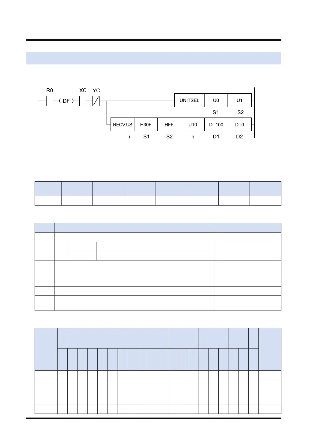
Ladder diagram
(Note 1) The above figure shows the case that S1=U0 (CPU unit with built-in SCU) and S2=U1 (port number 1)
are specified by the UNITSEL instruction.
■
Available operation units (●: Available)
Operatio
n unit
bit US SS UL SL SF DF
i ● ●
■
List of operands
Items Settings Setting range
S1
MODBUS function code to be used, and the partner station number
Higher byte MODBUS function code (two hexadecimal digits) H1 to H4 (1 to 4)
Lower byte Partner station number (two hexadecimal digits) H1 to HFF (1 to 255)
S2 MODBUS starting address of the sender in the partner unit H0 to HFFFF (0 to 65535)
n Number of received data
1 to 127 words
1 to 2040 bits
D1 Device starting address of the receiver data area in the master unit -
D2
Starting address of the device area of the master unit that stores the
execution result code (1 word)
■
Available word devices (●: Available)
Operan
d
16-Bit device:
32-Bit
device:
Integer
Real
numbe
r
St
rin
g
Index
modifie
r
W
X
W
Y
W
R
W
L
W
S
S
D
D
T
L
D
U
M
WI
W
O
TS
C
S
TE
C
E
IX K U H SF
D
F
" "
S1 ● ● ● ● ● ● ● ● ●
S2 ● ● ● ● ● ● ●
(N
ote
1)
●
n ● ● ● ● ● ● ● ● ●
15.7 RECV (MODBUS Master: Function Code Specification)
15-44 WUME-FP7CPUPGR-12

 Loading...


