● As a rule, when you specify the relay as an output destination for an OT↑ or OT↓ instruction,
the specification is limited to once in a program. (Double output is prohibited)
● When used as contacts, there are no restrictions on the number of times that can be used.
● A pulse relay cannot be specified as an output destination for an OT, KP, SET, RST or ALT
instruction.
● A word unit pulse relay (WP) cannot be specified as a storage location for a high-level
instruction.
2.5.9 E Error alarm relay
■
How error alarm relay (E) works
● Error alarm relays are used to feed back error conditions freely assigned by the user to
internal relays, and to store them in memory.
● Error alarm relays are turned ON and OFF using the SET and RST instructions in the user
program.
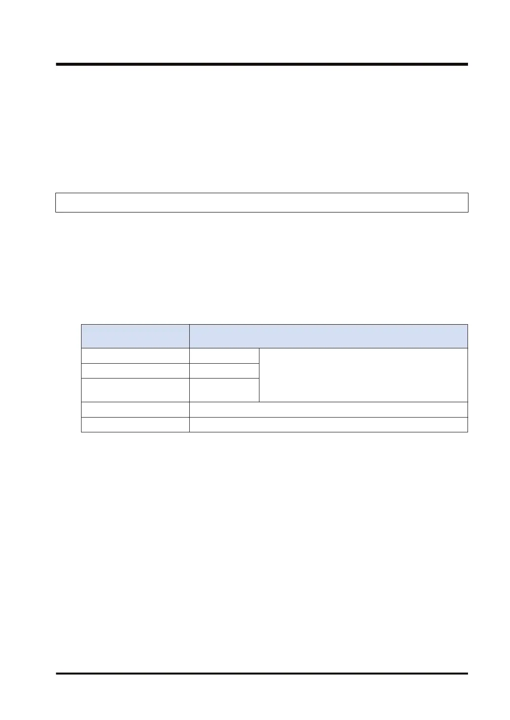
● When an error alarm relay goes ON, the number of error alarm relays which are on, the relay
numbers, and the data of the calendar timer which went on first are stored in a memory area
in the CPU unit.
System data register SD
No.
Description
SD80, SD81 Year/month data
Data for the calendar timer when the relay was initially
turned ON
SD82, SD83 Day/hour data
SD84, SD85
Minute/second
data
SD60 Number of relays that are turned ON
SD61 to SD79 Number of relays that are turned ON
● Information for up to 500 error alarm relays can be stored in the memory area. Relays that
can be monitored or operated by the user, however, are those in the range from SD61 to
SD79 only.
■
Usage restrictions
● An error alarm relay (E) cannot be specified as an output destination for an OT, KP, or ALT
instruction.
● An error alarm relay (E) can be turned ON and OFF in multiple locations in the program,
using the SET and RST instructions. However, no check is carried out for overlapping use.
■
Program for setting (turning on) an error alarm relays
● The SET instruction should be used to turn ON error alarm relays in the error alarm
conditions, as shown below.
● Error alarm relays are held even if the error condition goes OFF.
2.5 Explanations about Relays
WUME-FP7CPUPGR-12 2-23

 Loading...


