3.42 ICLR (Unit Interruption Clear)
■
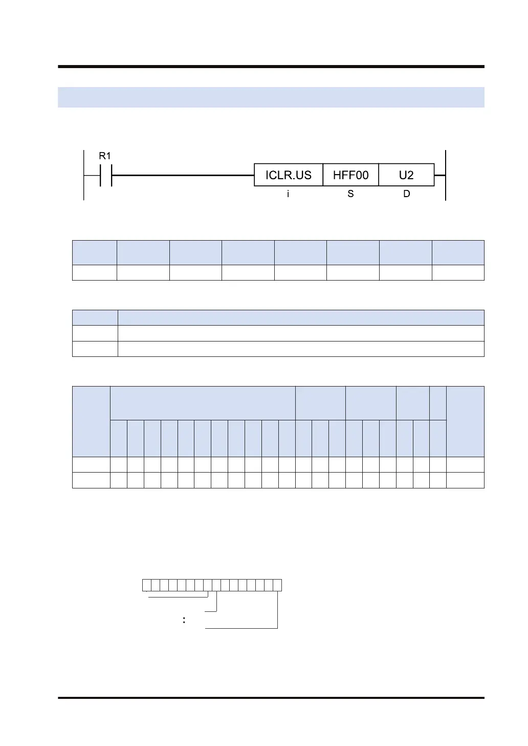
Ladder diagram
■
Available operation units (●: Available)
Operatio
n unit
bit US SS UL SL SF DF
i ●
■
List of operands
Operand Description
S Control data specifying INTPG number to clear interruption: HFF00 to HFFFF
D Slot number (U constant) or device number where slot number is stored
■
Devices that can be specified (indicated by ●)
Operan
d
16-Bit device:
32-Bit
device:
Integer
Real
numbe
r
St
rin
g
Index
modifie
r
W
X
W
Y
W
R
W
L
W
S
S
D
D
T
L
D
U
M
WI
W
O
TS
C
S
TE
C
E
IX K U H SF
D
F
" "
S ● ● ● ● ● ● ● ● ● ● ● ●
D ● ● ● ● ● ● ● ● ● ● ● ●
■
Outline of operation
● This instruction clears the interruption of the unit installed in the slot specified by [D]
according to the data specified by [S].
■
Specification of [S]
INTPG 7
INTPG 0
1 1 1 1 1 1 1 1
8 7
Higher 8 bits 1: Fixed
3.42 ICLR (Unit Interruption Clear)
WUME-FP7CPUPGR-12 3-125

 Loading...


