10.14 RAMP (Ramp Output)
■
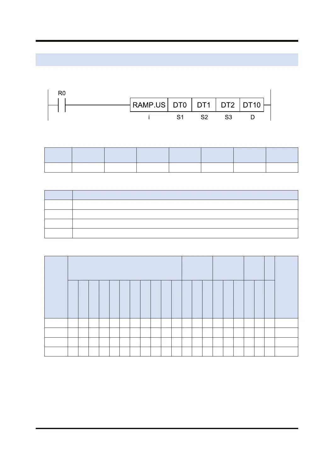
Ladder diagram
■
Available operation units (●: Available)
Operatio
n unit
bit US SS UL SL SF DF
i ● ● ● ● ● ●
■
List of operands
Operand Description
S1 Device address where the default is stored, or constant
S2 Device address where the target value is stored, or constant
S3 Device address that stores the time width, or the constant (data available range: 1 to 30000)
D Output storage device address
■
Available devices (●: Available)
Operan
d
16-Bit device:
32-Bit
device:
(Note 1)
Integer
Real
numbe
r
St
rin
g
Index
modifie
r
(Note 2)
W
X
W
Y
W
R
W
L
W
S
S
D
D
T
L
D
U
M
WI
W
O
TS
C
S
TE
C
E
IX
(N
ote
3)
K
(N
ote
4)
U
(N
ote
5)
H
(N
ote
6)
SF
(N
ote
7)
D
F
(N
ote
8)
" "
S1 ● ● ● ● ● ● ● ● ● ● ● ● ● ● ●
S2 ● ● ● ● ● ● ● ● ● ● ● ● ● ● ●
S3 ● ● ● ● ● ● ● ● ● ● ● ● ● ● ●
D ● ● ● ● ● ● ● ● ● ●
(Note 1) Cannot be specified when the operation unit is 16-bit integer (SS, US).
(Note 2) Only 16-bit devices, 32-bit devices, and integer constants can be modified. (Real number constants,
and character constants cannot be specified.)
(Note 3) Index register (I0 to IE)
(Note 4) Can be specified only when the operation unit is signed integer (SS, SL).
(Note 5) Can be specified only when the operation unit is unsigned integer (US, UL).
(Note 6) Can be specified only when the operation unit is integer (US, SS, UL, SL).
(Note 7) Can be specified only when the operation unit is a single-precision floating point real number (SF).
10.14 RAMP (Ramp Output)
WUME-FP7CPUPGR-12 10-57

 Loading...


