15.8 PMSET / pPMSET (Change of SCU Parameters)
■
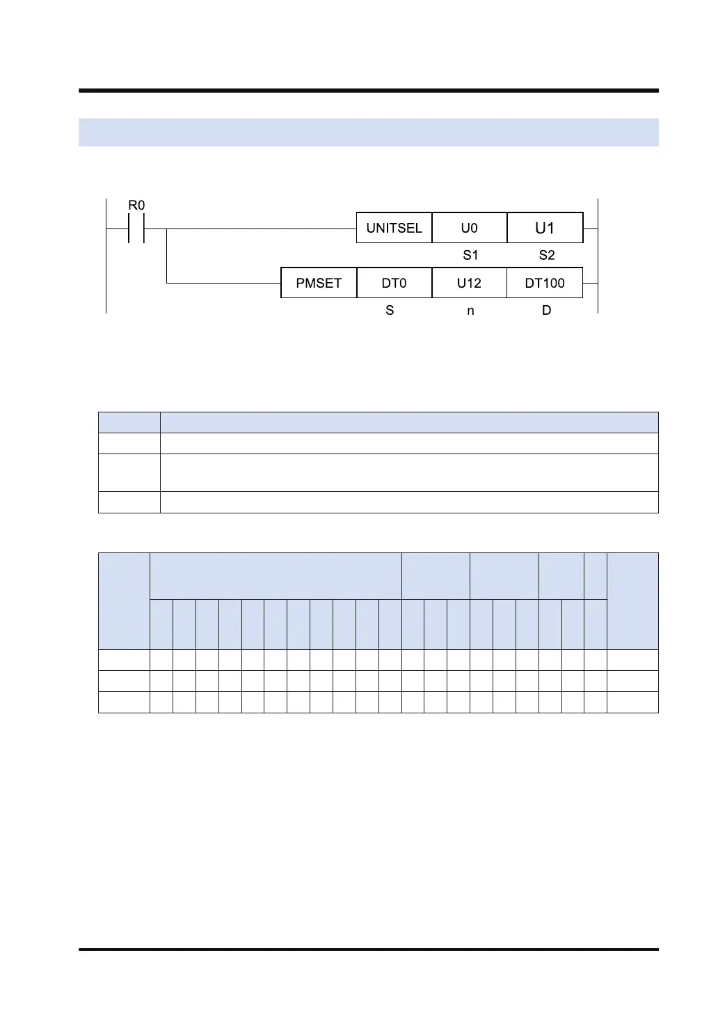
Ladder diagram
(Note 1) The above figure shows the case that S1=U0 (CPU unit with built-in SCU) and S2=U1 (port number 1)
are specified by the UNITSEL instruction.
■
List of operands
Operand Description
S Start of the area that stores data to be set as communication parameters
n
Specified number of words
Other than PLC link mode (setting range: 1 to 12). PLC link mode (setting range: 1 to 26)
D Starting address of the device area in the master unit that stores the processing result (1 word)
■
Available devices (●: Available)
Operan
d
16-Bit device:
32-Bit
device:
Integer
Real
numbe
r
St
rin
g
Index
modifie
r
W
X
W
Y
W
R
W
L
W
S
S
D
D
T
L
D
U
M
WI
W
O
TS
C
S
TE
C
E
IX K U H SF
D
F
" "
S ● ● ● ● ● ● ●
n ● ● ● ● ● ● ● ●
D ● ● ● ● ● ● ●
■
Outline of operation
● Communication parameters of the COM port of the unit is changed with a user program.
● Set communication parameters to be changed within [n] words from the area starting with
[S], and execute the PMSET/pPMSET instruction, to issue the setting change request to the
unit.
● While the requested change is being processed, bit 15 of the processing result storage area
[D] turns ON. When the process is completed, it turns OFF.
● The processing result is stored in the area specified by [D]. If there is any abnormality, bit 14
of [D] turns ON. The error code is stored in low bytes of [D].
● By reading setting parameters using the PMGET instruction, and setting parameters to be
changed using the PMSET/pPMSET instruction, the settings can be simplified.
15.8 PMSET / pPMSET (Change of SCU Parameters)
WUME-FP7CPUPGR-12 15-51

 Loading...


