9.2 BTR (16-bit Data Specified Bit Reset)
■
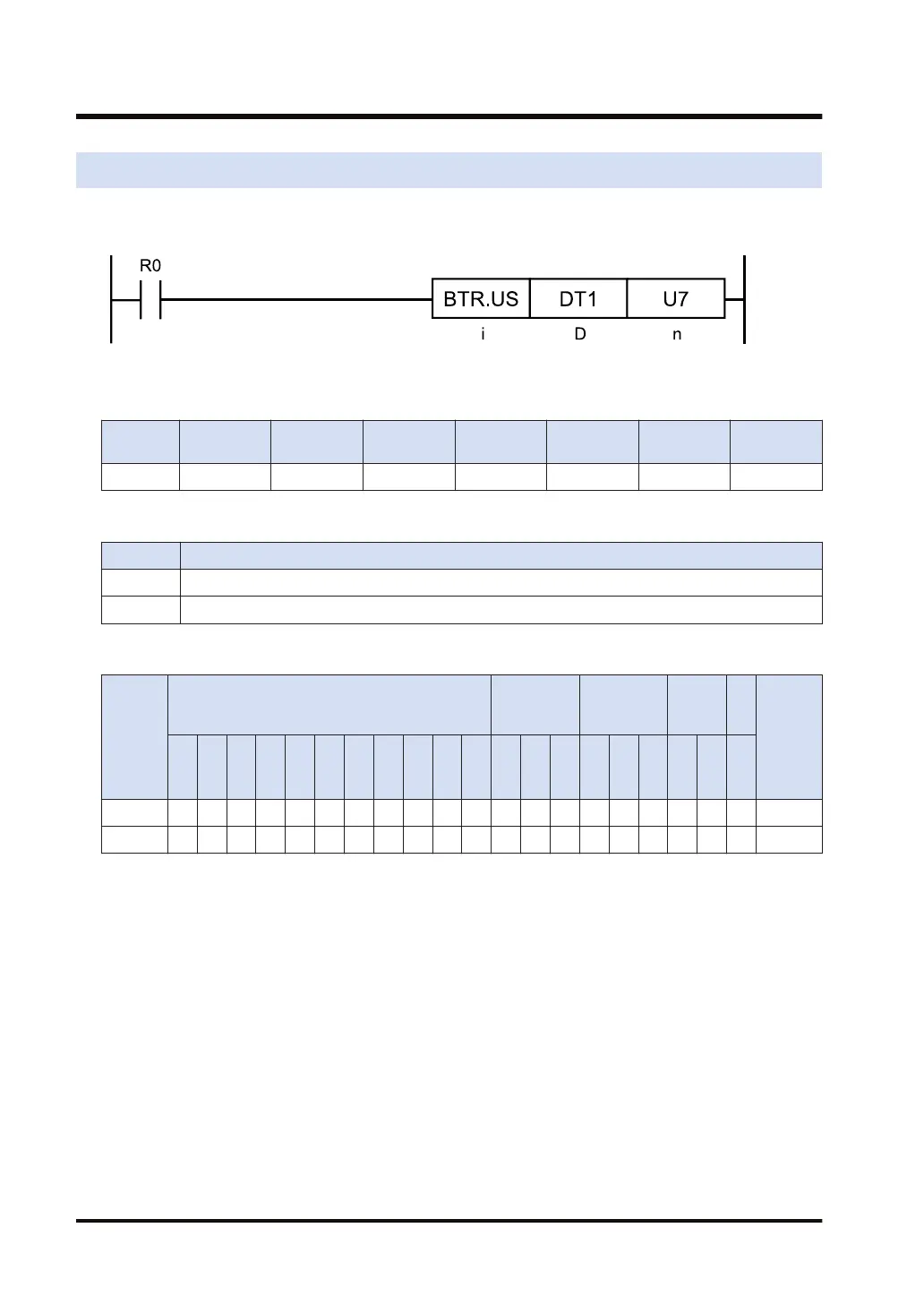
Ladder diagram
■
Available operation units (●: Available)
Operatio
n unit
bit US SS UL SL SF DF
i ●
■
List of operands
Operand Description
D Device address of target data
n Bit number (device address or constant) (available range: 0 to 15)
■
Available devices (●: Available)
Operan
d
16-Bit device:
32-Bit
device:
Integer
Real
numbe
r
St
rin
g
Index
modifie
r
(Note 1)
W
X
W
Y
W
R
W
L
W
S
S
D
D
T
L
D
U
M
WI
W
O
TS
C
S
TE
C
E
IX K U H SF
D
F
" "
D ● ● ● ● ● ● ● ● ●
n ● ● ● ● ● ● ● ● ● ● ● ●
(Note 1) Only 16-bit devices, 32-bit devices, and integer constants can be modified. (Real number constants,
and character constants cannot be specified.)
■
Outline of operation
● This instruction turns OFF (0) the [n]th bit in the area specified by [D].
● Other bits except the bit specified by [n] do not change.
● [n] is in the range of U0 to U15.
■
Processing
Example 1) Specifying a constant for the bit number
[D]...DT0 [n]...U4
9.2 BTR (16-bit Data Specified Bit Reset)
9-4 WUME-FP7CPUPGR-12

 Loading...


