3.24 LRSR (Left/Right Shift Register)
■
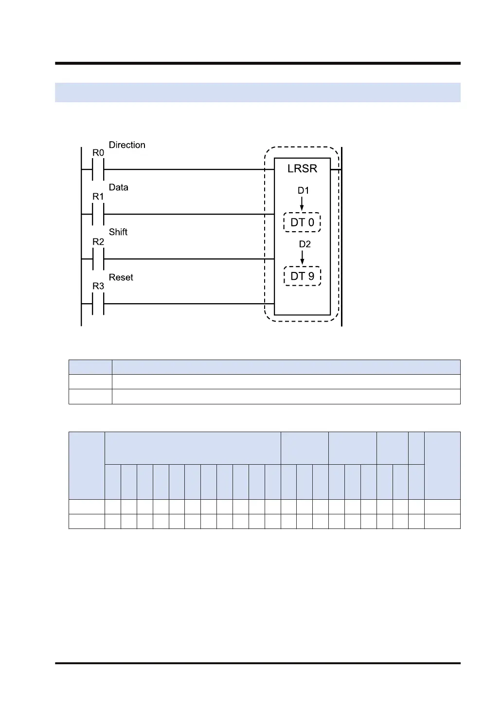
Ladder diagram
■
List of operands
Operand Description
D1 Shift starting position
D2 Shift ending position
■
Devices that can be specified (indicated by ●)
Operan
d
16-Bit device:
32-Bit
device:
Integer
Real
numbe
r
St
rin
g
Index
modifie
r
W
X
W
Y
W
R
W
L
W
S
S
D
D
T
L
D
U
M
WI
W
O
TS
C
S
TE
C
E
IX K U H SF
D
F
" "
D1 ● ● ● ● ● ● ● ●
D2 ● ● ● ● ● ● ● ●
■
Outline of operation
● Left/right shift is a shift register which shifts one bit of the specified data area to the left (to
the higher bit position) or to the right (to the lower bit position), depending on the ON/OFF
state of the relay specified as the left/right shift input.
● The shift operation is made to the left when the left/right shift input is ON, and to the right
when OFF.
● Specify the same type of memory area for [D1] and [D2]. Additionally, specify values so that
[D1] is equal to or less than [D2].
3.24 LRSR (Left/Right Shift Register)
WUME-FP7CPUPGR-12 3-73

 Loading...


