8.17 DEFBUF (Buffer Definition)
■
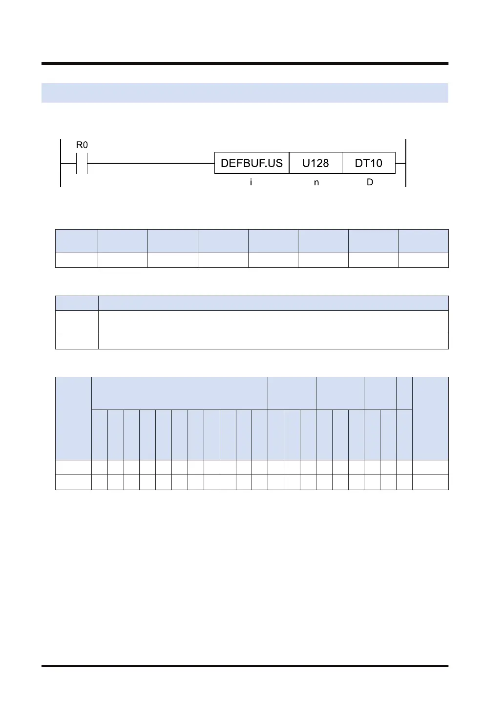
Ladder diagram
■
Available operation units (●: Available)
Operatio
n unit
bit US SS UL SL SF DF
i ● ●
■
List of operands
Operand Description
n
The device address which specifies the buffer size, or the constant (available data range: 1 to
4096)
D Starting device address of the data buffer
■
Available devices (●: Available)
Operan
d
16-Bit device:
32-Bit
device:
Integer
Real
numbe
r
St
rin
g
Index
modifie
r
(Note 1)
W
X
W
Y
W
R
W
L
W
S
S
D
D
T
L
D
U
M
WI
W
O
TS
C
S
TE
C
E
IX
(N
ote
2)
K
(N
ote
3)
U
(N
ote
4)
H SF
D
F
" "
n ● ● ● ● ● ● ● ● ● ● ● ●
D ● ● ●
(Note 1) Only 16-bit devices and integer constants can be modified.
(Note 2) Index register (I0 to IE)
(Note 3) Can be specified only when the operation unit is signed integer (SS, SL).
(Note 4) Can be specified only when the operation unit is unsigned integer (US, UL).
■
Outline of operation
● According to the operation unit [i], the instruction defines the data buffer to be for [n] data
starting from the [D] area.
● From ([D]+1) (usable size) to ([D]+3) (write pointer) are initialized (cleared to zero).
8.17 DEFBUF (Buffer Definition)
8-34 WUME-FP7CPUPGR-12

 Loading...


