3.33 ZRST (Clear Multiple Processes)
■
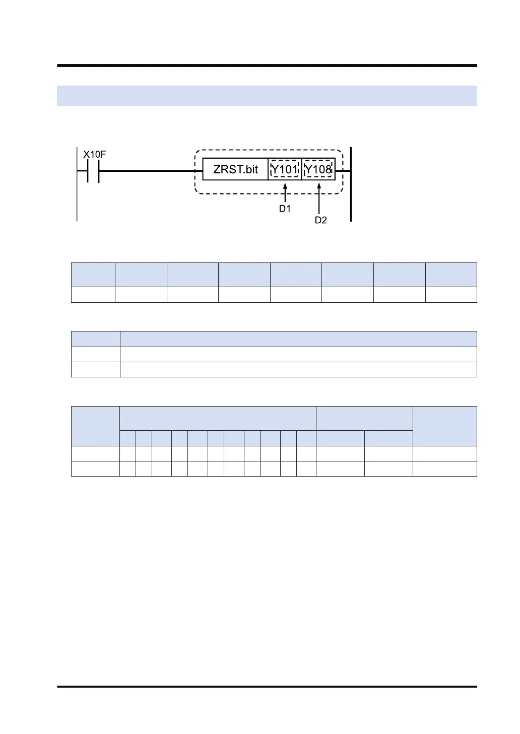
Ladder diagram
■
Available operation units (●: Available)
Operatio
n unit
bit US SS UL SL SF DF
i ●
■
List of operands
Operand Description
D1 Process clear start number
D2 Process clear end number
■
Devices that can be specified (indicated by ●)
Operand
Bit device
Specification of bit of
word device
Index modifier
X Y R L T C P E SR IN OT DT.n LD.n
D1 ● ● ● ● ● ● ● ●
D2 ● ● ● ● ● ● ● ●
■
Outline of operation
● When the ZRST instruction is executed, all the running processes within the range from the
process [D1] and [D2] will be cleared.
● It can also be used to reset (clear to zero) the range from the area (bit address) specified in
[D1] to the area (bit address) specified in [D2].
■
Precautions for programming
● Be sure that [D1] is smaller than [D2].
● This instruction can be executed from the normal ladder area as well as a running process.
3.33 ZRST (Clear Multiple Processes)
WUME-FP7CPUPGR-12 3-105

 Loading...


