7.17 LINE (Conversion: Bit Column → Bit Line)
■
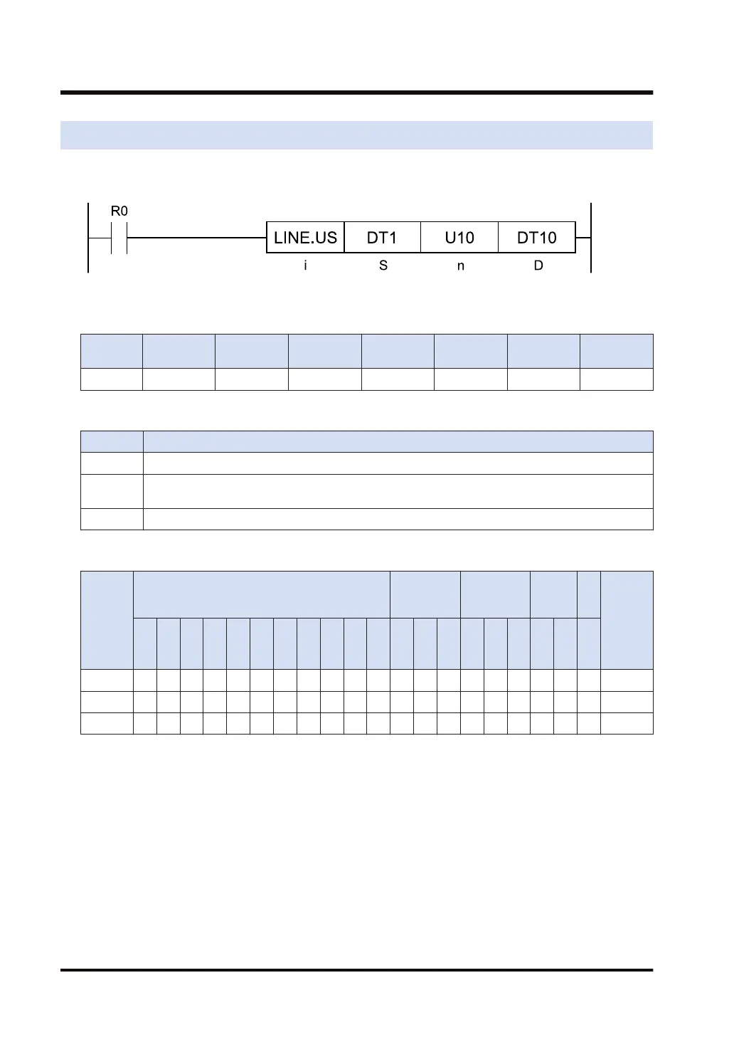
Ladder diagram
■
Available operation units (●: Available)
Operatio
n unit
bit US SS UL SL SF DF
i ●
■
List of operands
Operand Description
S Starting address of the device whose bit column is read.
n
The device address where the specification for the bit position is stored, or the constant (available
data range: 0 to 15)
D Storage device address
■
Available devices (●: Available)
Operan
d
16-Bit device:
32-Bit
device:
Integer
Real
numbe
r
St
rin
g
Index
modifie
r
(Note 1)
W
X
W
Y
W
R
W
L
W
S
S
D
D
T
L
D
U
M
WI
W
O
TS
C
S
TE
C
E
IX K U H SF
D
F
" "
S ● ● ● ● ● ● ● ● ● ● ● ●
n ● ● ● ● ● ● ● ● ● ● ● ● ● ●
D ● ● ● ● ● ● ● ● ●
(Note 1) Only 16-bit devices, and integer constants can be modified. (Real number constants, and character
constants cannot be specified.)
■
Outline of operation
● The [n]-bit column data, in the 16-word device area specified by [S], are transferred to the
16-bit data specified by [D].
■
Processing
Example) Operation unit: 16 bits (US)
[i]...US
[S]...DT1 [n]...U10 [D]...DT20
7.17 LINE (Conversion: Bit Column → Bit Line)
7-38 WUME-FP7CPUPGR-12

 Loading...


