■
Precautions for use
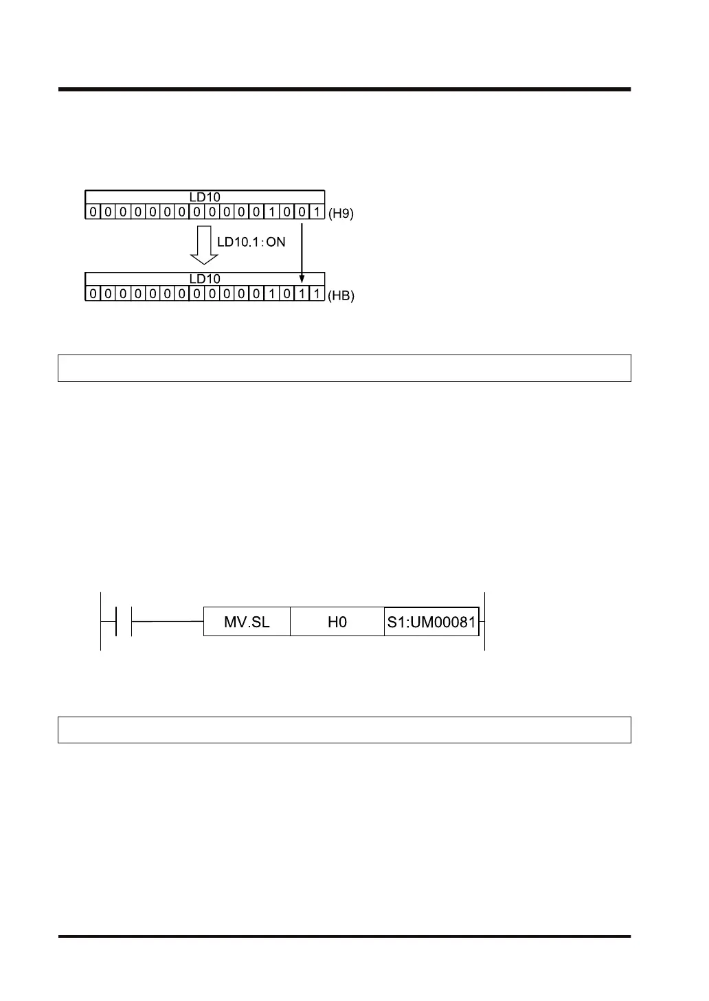
● If the ON/OFF status changes for any of the bit data of the link register (LD*.n), the value of
the link register (LD) also changes.
2.6.5 UM Unit memory
■
How unit memory (UM) works
● Unit memory is used to send and receive data between CPU units and intelligent units.
● The amount of data in unit memory and its allocation varies depending on the type of unit.
● The address for the unit memory is specified as a 5-digit hexadecimal. (H 0 to H 7FFFF
(Maximum))
● In the program, an address is specified with a corresponding slot number (S1, S2...).
■
Unit memory (UM) usage example
● The following is an example of transferring the constant H0 to the address H 00081 of the
unit memory (UM) of slot number 1.
2.6.6 SD System data register
■
How system data register (SD) works
● System data register is a memory area in which designated contents are stored.
● There are three types of areas: an area for read-only, an area for read-and-write, and an
area used by the system.
● The types of system data registers are as follows.
2.6 Description of the memory area
2-30 WUME-FP7CPUPGR-12

 Loading...


