8.19 BUFW (Data Write)
■
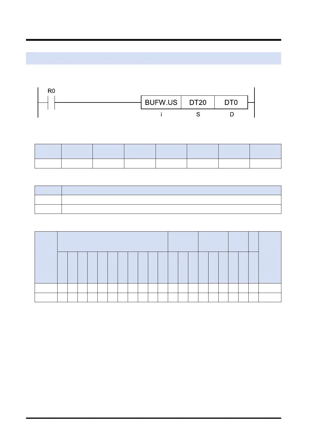
Ladder diagram
■
Available operation units (●: Available)
Operatio
n unit
bit US SS UL SL SF DF
i ● ●
■
List of operands
Operand Description
S The device address of the write data, or the constant
D Starting device address of the data buffer
■
Available devices (●: Available)
Operan
d
16-Bit device:
32-Bit
device:
Integer
Real
numbe
r
St
rin
g
Index
modifie
r
(Note 1)
W
X
W
Y
W
R
W
L
W
S
S
D
D
T
L
D
U
M
WI
W
O
TS
C
S
TE
C
E
IX
(N
ote
2)
K
(N
ote
3)
U
(N
ote
4)
H SF
D
F
" "
S ● ● ● ● ● ● ● ● ● ● ● ● ● ● ●
D ● ● ●
(Note 1) Only 16-bit devices and integer constants can be modified.
(Note 2) Index register (I0 to IE)
(Note 3) Can be specified only when the operation unit is signed integer (SS, SL).
(Note 4) Can be specified only when the operation unit is unsigned integer (US, UL).
■
Outline of operation
● This instruction sets the data specified by [S] to the buffer specified by [D].
(In the [D] buffer area, it is necessary to define buffer first using the DEFBUF instruction.)
● Pre-execution buffer consistency check (An operation error occurs in the following cases)
1. [D] (buffer size) > 4096, or [D] (buffer size) = 0
2. [D]+1 (stored data amount) ≥ [D] (buffer size)
3. [D]+3 (write pointer) ≥ [D] (buffer size)
4. Buffer area exceeds the upper limit of the specified device
8.19 BUFW (Data Write)
8-40 WUME-FP7CPUPGR-12

 Loading...


