16.5 PMGET (Acquiring MEWNET-F Parameters)
■
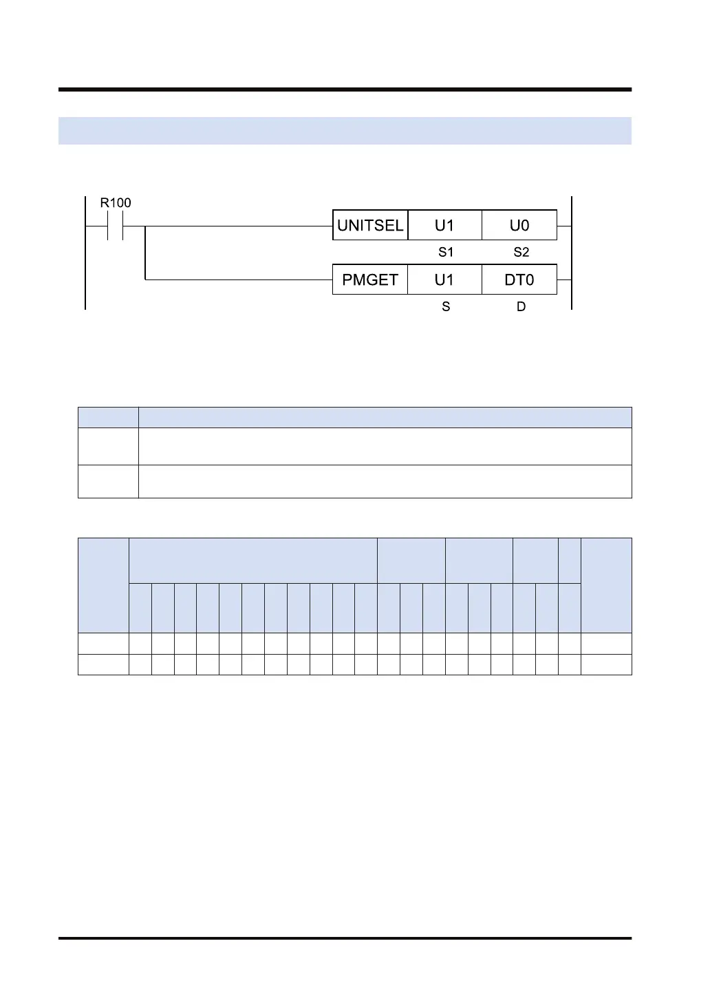
Ladder diagram
(Note 1) The above figure shows the case that the FP7 multi-wire link unit for S1=U1 (slot number 1) is
specified by the UNITSEL instruction.
■
List of operands
Operand Description
S
Type of acquired data
0: Number of F link services, 1: F link operation state monitor
D
Starting address of the area that stores the acquired communication parameter (monitor
information)
■
Available devices (●: Available)
Operan
d
16-Bit device:
32-Bit
device:
Integer
Real
numbe
r
St
rin
g
Index
modifie
r
W
X
W
Y
W
R
W
L
W
S
S
D
D
T
L
D
U
M
WI
W
O
TS
C
S
TE
C
E
IX K U H SF
D
F
" "
S ● ● ● ● ● ● ● ●
D ● ● ● ● ● ● ●
■
Outline of operation
● Monitor information showing the communication state can be acquired.
● MEWNET-F communication parameters of the FP7 multi-wire link unit are read and stored in
the area that starts with [D].
● Specify the type of acquired data in [S].
■
Precautions for programming
● Describe the UNITSEL instruction immediately before the PMGET instruction. Specify the
slot number of the unit from which the parameters are acquired for [S1] and specify 0 for
[S2].
● The size of the area storing data varies in the range of 1 to 10 words according to the data
type specified in [S].
16.5 PMGET (Acquiring MEWNET-F Parameters)
16-18 WUME-FP7CPUPGR-12

 Loading...


