5.5 BKMV (Block Transfer)
■
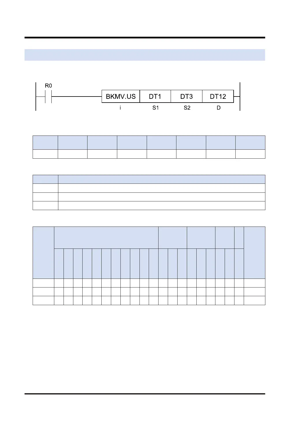
Ladder diagram
■
Available operation units (●: Available)
Operatio
n unit
bit US SS UL SL SF DF
i ● ● ● ● ● ●
■
List of operands
Operand Description
S1 Starting device address of source data
S2 Ending device address of source data
D Destination starting device address to transfer data
■
Available devices (●: Available)
Operan
d
16-Bit device:
32-Bit
device:
(Note 1)
Integer
Real
numbe
r
St
rin
g
Index
modifie
r
W
X
W
Y
W
R
W
L
W
S
S
D
D
T
L
D
U
M
WI
W
O
TS
C
S
TE
C
E
IX
(N
ote
2)
K U H SF
D
F
" "
S1 ● ● ● ● ● ● ● ● ● ● ● ● ● ● ●
S2 ● ● ● ● ● ● ● ● ● ● ● ● ● ● ●
D ● ● ● ● ● ● ● ● ● ● ● ●
(Note 1) Cannot be specified when the operation unit is 16-bit integer (SS, US).
(Note 2) Index register (I0 to IE)
■
Outline of operation
● This instruction transfers data in the area specified by [S1] to [S2] to the area specified by [D]
and subsequent areas all at once.
5.5 BKMV (Block Transfer)
5-10 WUME-FP7CPUPGR-12

 Loading...


