14.7 BINA (Conversion: BIN → Decimal ASCII)
■
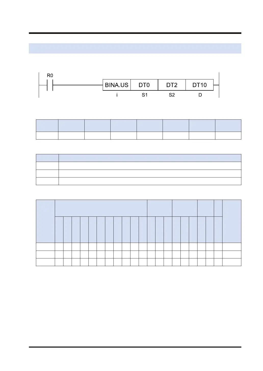
Ladder diagram
■
Available operation units (●: Available)
Operatio
n unit
bit US SS UL SL SF DF
i ● ● ● ●
■
List of operands
Operand Description
S1 The area that stores the BIN data that express a decimal figure, or the constant
S2 The area that stores the number of bytes of the area to store the conversion result, or the constant
D Starting number of the area that stores the ASCII code as the conversion result
■
Available devices (●: Available)
Operan
d
16-Bit device:
32-Bit
device:
Integer
Real
numbe
r
St
rin
g
Index
modifie
r
(Note 1)
W
X
W
Y
W
R
W
L
W
S
S
D
D
T
L
D
U
M
WI
W
O
TS
C
S
TE
C
E
IX
K
(N
ote
2)
U
(N
ote
3)
H
(N
ote
4)
SF
D
F
" "
S1 ● ● ● ● ● ● ● ● ● ● ● ●
S2 ● ● ● ● ● ● ● ● ● ●
D ● ● ● ● ● ● ●
(Note 1) Only 16-bit devices, 32-bit devices, and integer constants can be modified. (Real number constants,
and character constants cannot be specified.)
(Note 2) Can be specified only when the operation unit is signed integer (SS, SL).
(Note 3) Can be specified only when the operation unit is unsigned integer (US, UL).
(Note 4) Can be specified only when the operation unit is an integer (US, SS, UL, SL).
■
Outline of operation
● This instruction converts BIN data that expresses a decimal figure into an ASCII code string.
● The BIN data expressed as a decimal figure specified by [S1] is converted into an ASCII
code and stored in the area specified by [D].
● The start of the storage area is specified by [D] and its size is specified by [S2].
14.7 BINA (Conversion: BIN → Decimal ASCII)
WUME-FP7CPUPGR-12 14-23

 Loading...


