14.9 BTOA (Conversion: BIN → ASCII)
■
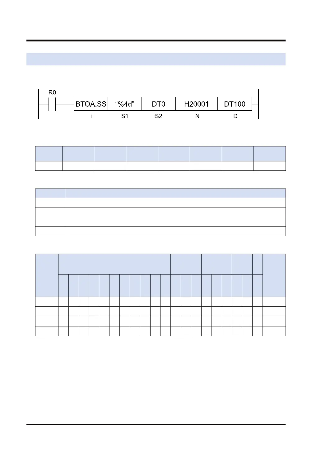
Ladder diagram
■
Available operation units (●: Available)
Operatio
n unit
bit US SS UL SL SF DF
i ● ● ● ● ● ●
■
List of operands
Operand Description
S1 Control string (2 to 16 characters)
S2 Starting address of the device that stores binary data
N Conversion method
D Starting address of the device that stores the ASCII code as the conversion result
■
Available devices (●: Available)
Operan
d
16-Bit device:
32-Bit
device:
Integer
Real
numbe
r
St
rin
g
Index
modifie
r
W
X
W
Y
W
R
W
L
W
S
S
D
D
T
L
D
U
M
WI
W
O
TS
C
S
TE
C
E
IX K U H SF
D
F
" "
S1 ● ● ● ● ● ● ●
S2 ● ● ● ● ● ● ● ● ●
N
(Note 1)
● ● ● ● ● ● ● ● ●
D ● ● ● ● ● ● ●
(Note 1) To be handled as a 32-bit integer (UL), regardless of operation unit.
■
Outline of operation
● This instruction converts the binary data stored in the area starting with [S2] into ASCII
codes.
● For [S1], specify the type, number of digits, and precision of the data to be converted.
● For [N], specify the number of data to be converted, the storage starting position, and the
conversion direction.
● The conversion result is stored in the area starting with [D].
14.9 BTOA (Conversion: BIN → ASCII)
14-30 WUME-FP7CPUPGR-12

 Loading...


