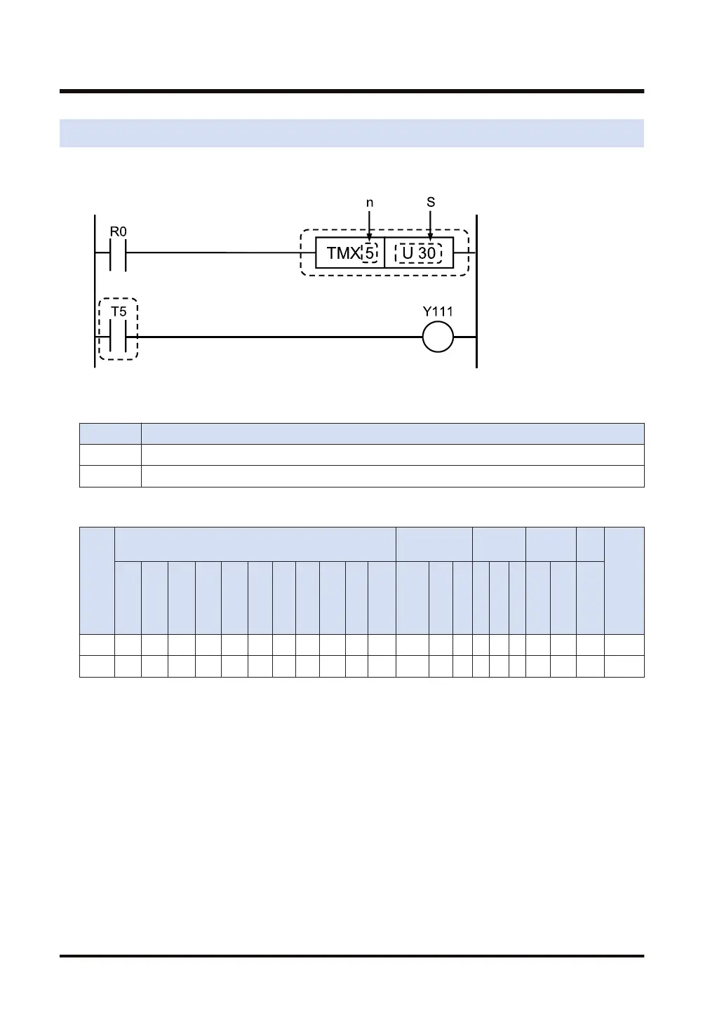
3.17 TM (Timer)
■
Ladder diagram
■
List of operands
Operand Description
n Timer number
S Timer set value
■
Devices that can be specified (indicated by ●)
Ope-
rand
16-Bit device:
32-Bit
device:
Integer
Real
number
Str-
ing
Index
mod-
ifier
(Note
2)
WX WY WR WL WS SD DT LD UM WI WO
TS
CS
(Note
1)
TE
CE
IX K U H SF DF " "
n ● ●
S ● ● ● ● ● ● ● ● ●
(Note 1) Only TS can be specified for TM instruction.
(Note 2) Only 16-bit devices, 32-bit devices, and integer constants can be modified. (Real number constants,
and character constants cannot be specified.)
■
Outline of operation
● The timer is the non-hold type that is reset when the power is turned off or the operation
mode is switched from RUN to PROG.
● When the execution condition is ON, the timer starts decrementing from the set time [S].
When the elapsed value reaches 0, the timer contact [Tn] (n is the timer contact number)
turns ON.
● When the execution condition turns OFF while the timer is decrementing, the timer stops and
resets the elapsed value (clears it to zero).
● The OT instruction can also be written immediately after a timer coil.
3.17 TM (Timer)
3-36 WUME-FP7CPUPGR-12

 Loading...


