17.6 CONSET (User Connection Setting)
■
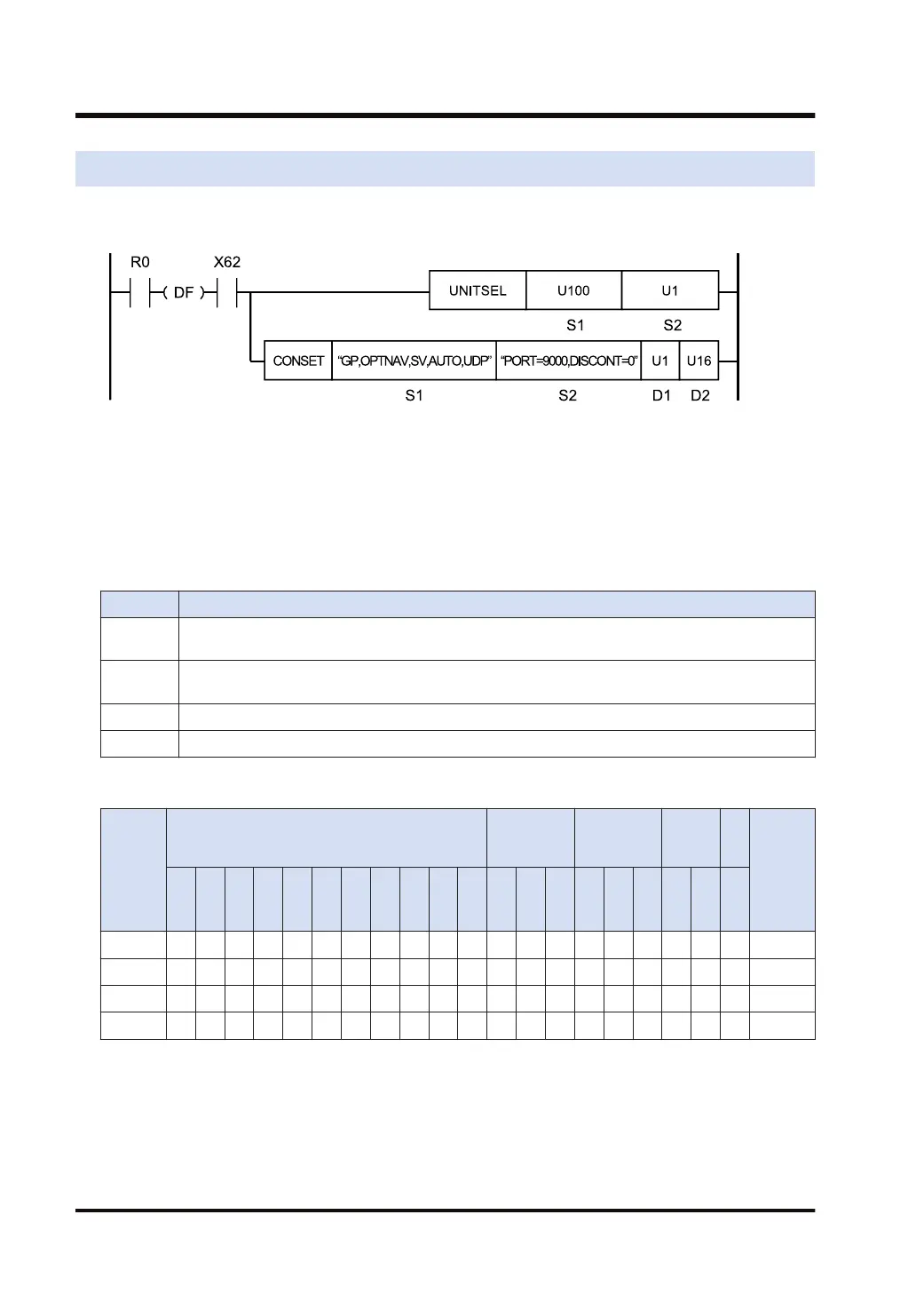
Ladder diagram
(Note 1) The above figure shows the case that S1=U100 (built-in ET-LAN in the CPU unit) and S2=U1
(connection number 1) are specified by the UNITSEL instruction.
(Note 2) By copying and pasting the following text in the instruction list box of FPWIN GR7, the operand part of
the above program can be input.
CONSET "GP,OPTNAV,SV,AUTO,UDP" "PORT=9000,DISCONT=0" U1 U16
■
List of operands
Operand Description
S1
Starting address of the device area that stores the string data that indicates the parameters for
operation setting, or a character constant.
S2
Starting address of the device area that stores the string data that indicates the parameters for port
setting, or a character constant.
D1 Device address where the setting start connection number is stored, or a constant
D2 Device address where the setting end connection number is stored, or a constant
■
Devices that can be specified (indicated by ●)
Operan
d
16-Bit device:
32-Bit
device:
Integer
Real
numbe
r
St
rin
g
Index
modifie
r
W
X
W
Y
W
R
W
L
W
S
S
D
D
T
L
D
U
M
WI
W
O
TS
C
S
TE
C
E
IX K U H SF
D
F
" "
S1 ● ● ● ● ● ● ●
S2 ● ● ● ● ● ● ●
D1 ● ● ● ● ● ● ● ● ●
D2 ● ● ● ● ● ● ● ● ●
■
Outline of operation
● This instruction sets the connection setting parameters that are specified by [S1] and [S2],
for the connections which are in the range specified by [D1] and [D2].
17.6 CONSET (User Connection Setting)
17-32 WUME-FP7CPUPGR-12

 Loading...


