8.13 RCR (Right Rotation of Data with Carry-Flag Data)
■
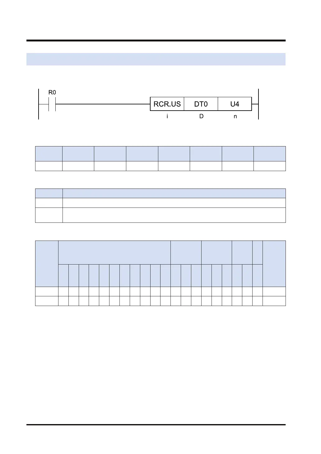
Ladder diagram
■
Available operation units (●: Available)
Operatio
n unit
bit US SS UL SL SF DF
i ● ●
■
List of operands
Operand Description
D The device address where the data to be rotated is stored
n
The device address where the number of rotation bits is stored, or the constant (Available data
range: 0 to 255)
■
Available devices (●: Available)
Operan
d
16-Bit device:
32-Bit
device:
(Note 1)
Integer
Real
numbe
r
St
rin
g
Index
modifie
r
(Note 2)
W
X
W
Y
W
R
W
L
W
S
S
D
D
T
L
D
U
M
WI
W
O
TS
C
S
TE
C
E
IX K U H SF
D
F
" "
D ● ● ● ● ● ● ● ● ● ● ● ●
n ● ● ● ● ● ● ● ● ● ● ● ● ● ● ●
(Note 1) Cannot be specified when the operation unit is 16-bit integer (US).
(Note 2) Only 16-bit devices, 32-bit devices, and integer constants can be modified. (Real number constants,
and character constants cannot be specified.)
■
Outline of operation
● This instruction rotates the data specified by [D] to the right (to the low bit position), by the
number of bits specified by [n] (decimal specification), with SR9 (CY).
● Only the lower 8 bits in data are available for [n]. The rotation amount is specified between 0
and 255 bits.
● (Rotation amount - 1) bits are output to SR9 (CY).
● When the operation unit is 16 bits (US), if [n] is either 0 or a multiple of 17, the rotation
amount is regarded as 0, and this instruction is not executed.
● When the operation unit is 32 bits (UL), if [n] is either 0 or a multiple of 33, the rotation
amount is regarded as 0, and this instruction is not executed.
8.13 RCR (Right Rotation of Data with Carry-Flag Data)
8-26 WUME-FP7CPUPGR-12

 Loading...


