10.3 MAX (Acquiring the Maximum Value)
■
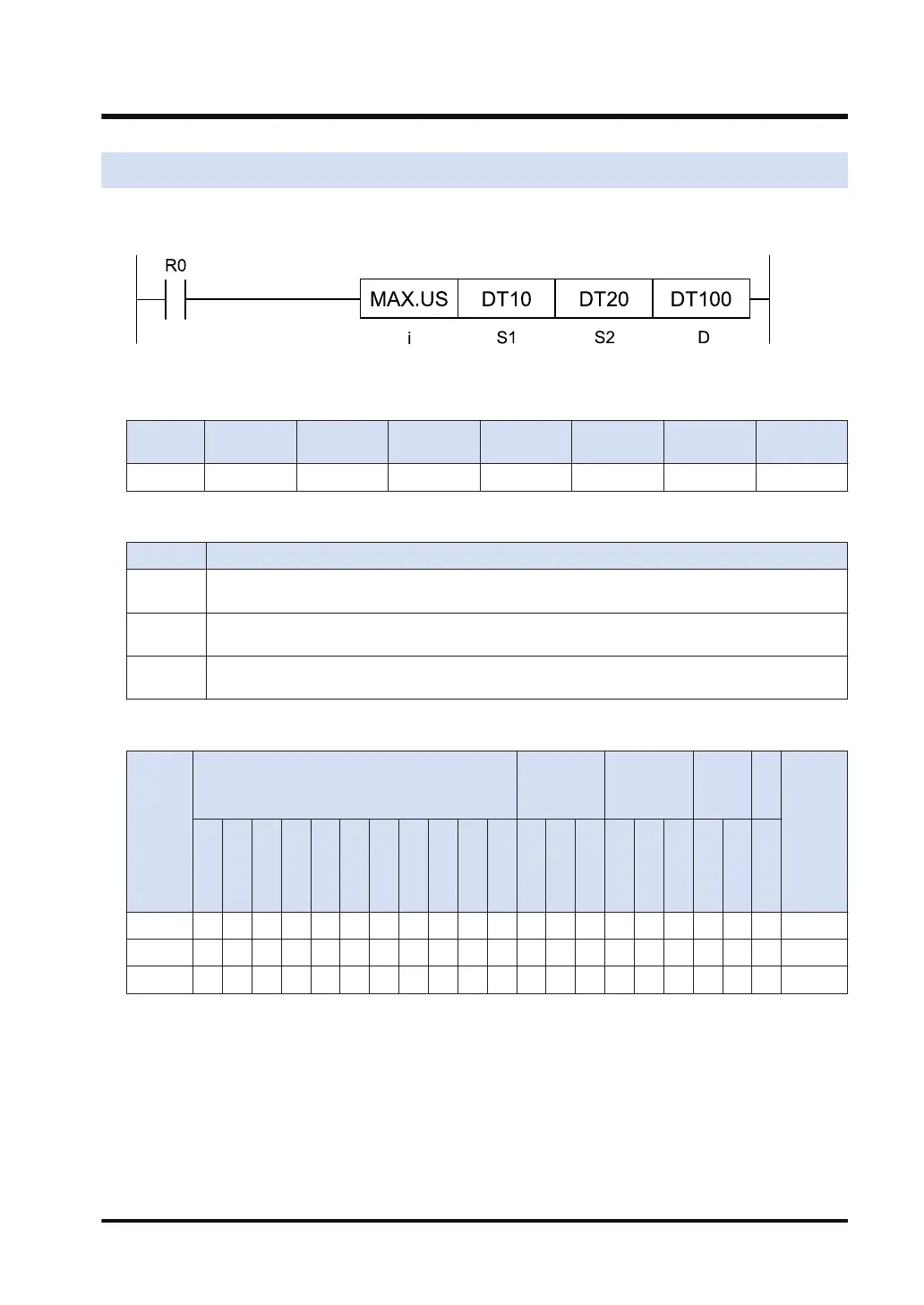
Ladder diagram
■
Available operation units (●: Available)
Operatio
n unit
bit US SS UL SL SF DF
i ● ● ● ● ● ●
■
List of operands
Operand Description
S1
Starting position of the search range for the maximum value (data format: according to the
operation unit)
S2
End position of the search range for the maximum value (data format: according to the operation
unit)
D
Device address to store the result of the search for the maximum value (data format: according to
the operation unit)
■
Available devices (●: Available)
Operan
d
16-Bit device:
32-Bit
device:
(Note 1)
Integer
Real
numbe
r
St
rin
g
Index
modifie
r
(Note 2)
W
X
W
Y
W
R
W
L
W
S
S
D
D
T
L
D
U
M
WI
W
O
TS
C
S
TE
C
E
IX
(N
ote
3)
K U H SF
D
F
" "
S1 ● ● ● ● ● ● ● ● ● ● ● ● ●
S2 ● ● ● ● ● ● ● ● ● ● ● ● ●
D ● ● ● ● ● ● ● ● ● ● ● ●
(Note 1) Cannot be specified when the operation unit is 16-bit integer (SS, US).
(Note 2) Only 16-bit devices, 32-bit devices, and integer constants can be modified. (Real number constants,
and character constants cannot be specified.)
(Note 3) Index register (I0 to IE)
■
Outline of operation
● The range of the device areas specified by [S1] and [S2] is searched for the maximum value.
● The resulting value is stored in the device area specified by [D], and the relative address
value from [S1] is stored in [n].
10.3 MAX (Acquiring the Maximum Value)
WUME-FP7CPUPGR-12 10-7

 Loading...


