17.2 ETSTAT (Acquiring Ethernet Unit Information: IP/MAC/Destination)
■
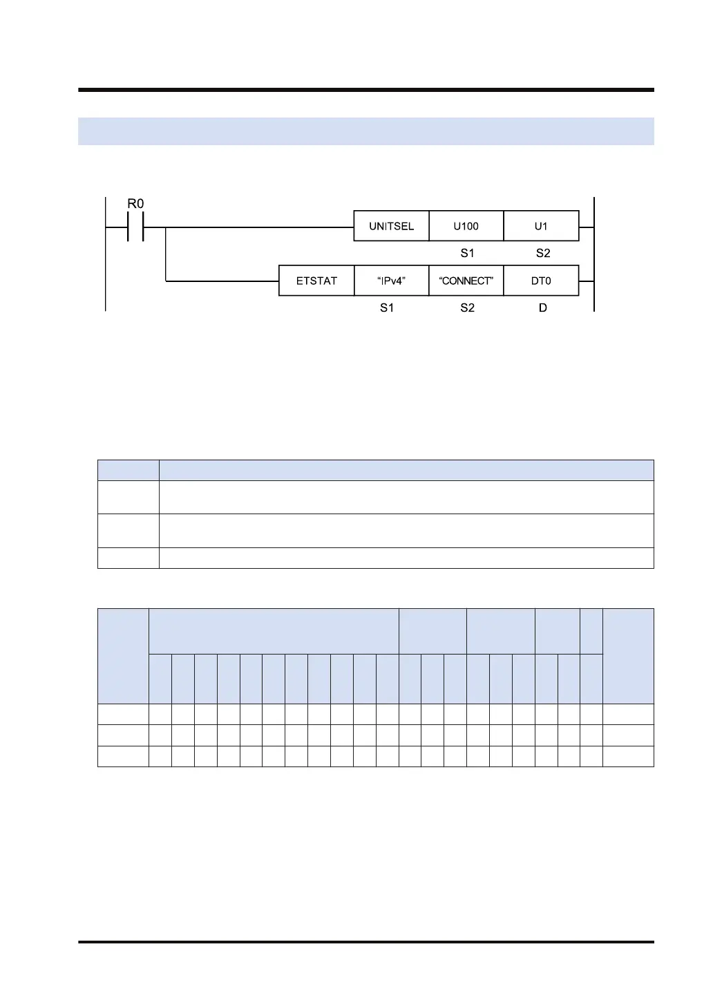
Ladder diagram
(Note 1) The above figure shows the case that S1=U100 (built-in ET-LAN in the CPU unit) and S2=U1
(connection number 1) are specified by the UNITSEL instruction.
(Note 2) By copying and pasting the following text in the instruction list box of FPWIN GR7, the operand part of
the above program can be input.
ETSTAT "IPv4" "CONNECT" DT0
■
List of operands
Operand Description
S1
Starting address of the device area that stores the string data that indicates a read type, or a
character constant.
S2
Starting address of the device area that stores the string data that indicates a target to be read, or a
character constant.
D Starting address of a readout destination device
■
Devices that can be specified (indicated by ●)
Operan
d
16-Bit device:
32-Bit
device:
Integer
Real
numbe
r
St
rin
g
Index
modifie
r
W
X
W
Y
W
R
W
L
W
S
S
D
D
T
L
D
U
M
WI
W
O
TS
C
S
TE
C
E
IX K U H SF
D
F
" "
S1 ● ● ● ● ● ● ●
S2 ● ● ● ● ● ● ●
D ● ● ● ● ● ●
■
Outline of operation
● This instruction reads the information of the Ethernet unit.
■
Processing
● The parameter information or status information specified by [S1] and [S2] is read and stored
in the area starting with [D].
● The number of words in the storage area varies according to the type of read data and the
target.
17.2 ETSTAT (Acquiring Ethernet Unit Information: IP/MAC/Destination)
WUME-FP7CPUPGR-12 17-5

 Loading...


