16.8 ERR (When FP7 Multi-wire Link Unit Is Used)
■
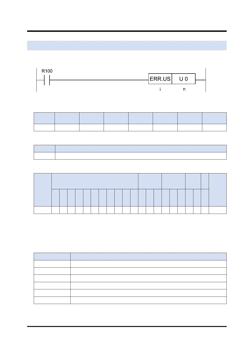
Ladder diagram
■
Available operation units (●: Available)
Operatio
n unit
bit US SS UL SL SF DF
i ●
■
List of operands
Operand Description
n Specify a self-diagnostic error code. (0: Clear the self-diagnostic error.)
■
Available devices (●: Available)
Operan
d
16-Bit device:
32-Bit
device:
Integer
Real
numbe
r
St
rin
g
Index
modifie
r
W
X
W
Y
W
R
W
L
W
S
S
D
D
T
L
D
U
M
WI
W
O
TS
C
S
TE
C
E
IX K U H SF
D
F
" "
n ● ●
■
Outline of operation
When the ERR instruction is executed with [n] set to U0, the instruction operates as follows:
● Clears errors in the FP7 multi-wire link unit.
● Resets the values of the system relays and the system data registers in the table shown
below.
Device No. Application
SR50 FP7 multi-wire link unit 1 error
SR51 FP7 multi-wire link unit 2 error
SR52 FP7 multi-wire link unit 3 error
SR53 FP7 multi-wire link unit 4 error
SR54 FP7 multi-wire link unit 5 error
SR55 FP7 multi-wire link unit 6 error
16.8 ERR (When FP7 Multi-wire Link Unit Is Used)
WUME-FP7CPUPGR-12 16-27

 Loading...


