10.12 EZPID (PID Operation: PWM Output Available)
■
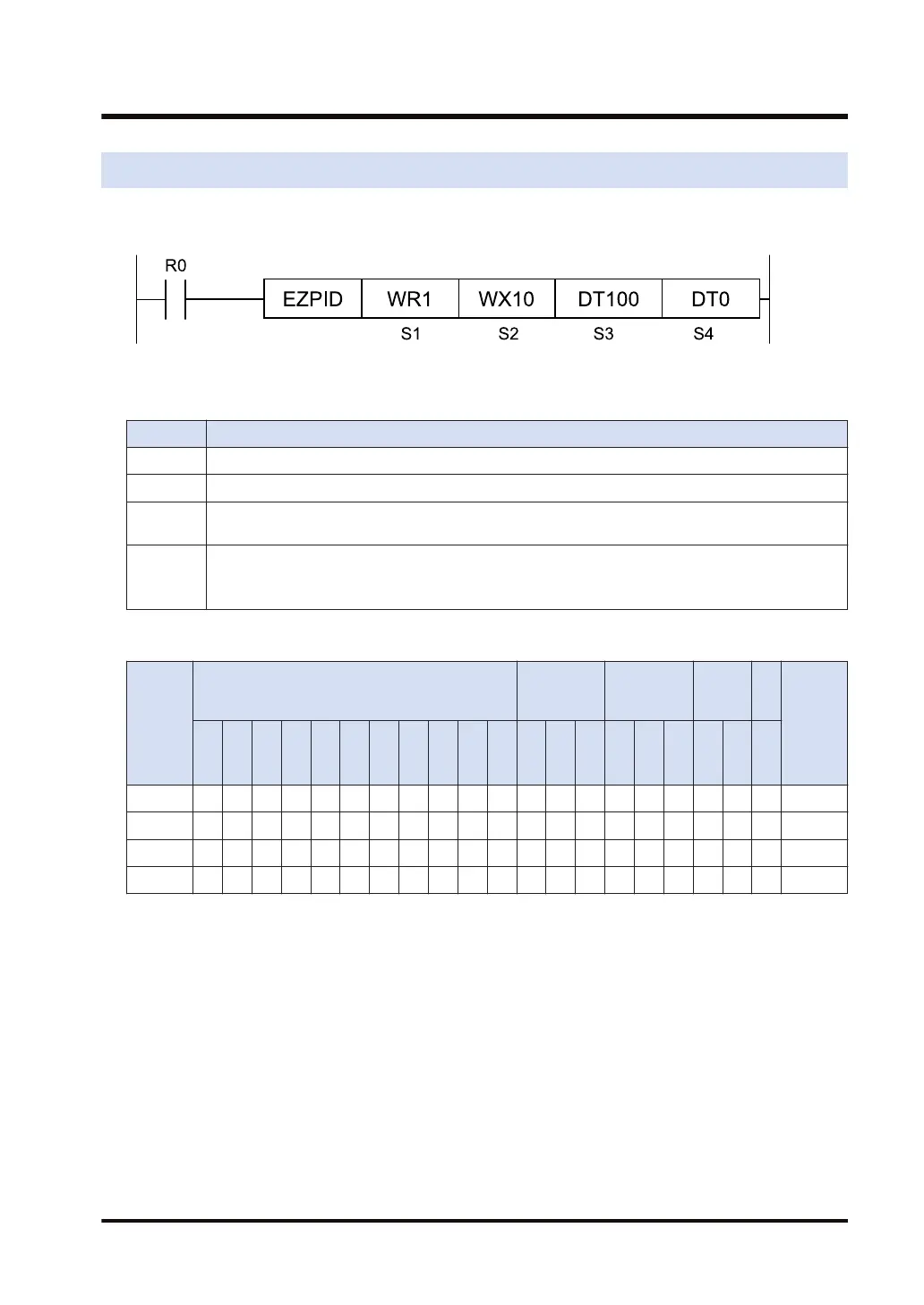
Ladder diagram
■
List of operands
Operand Description
S1 1-word area for setting control data that determine methods for auto-tuning and output
S2 1-word area for inputting the process value (PV)
S3
4-word area for setting the set point value (SV), proportional gain (Kp), integral time (Ti), and
derivative time (Td).
S4
30-word area comprising the following:
Storage area for the manipulated value (MV), control interval (Ts), control mode, setting area for
parameters related to auto-tuning, and operation work area
■
Devices that can be specified (indicated by ●)
Operan
d
16-Bit device:
32-Bit
device:
Integer
Real
numbe
r
St
rin
g
Index
modifie
r
W
X
W
Y
W
R
W
L
W
S
S
D
D
T
L
D
U
M
WI
W
O
TS
C
S
TE
C
E
IX K U H SF
D
F
" "
S1 ● ● ● ● ● ●
S2 ● ● ● ● ● ● ● ●
S3 ● ● ● ● ● ●
S4 ● ● ● ● ● ●
■
Outline of operation
● PID operation is carried out to retain the process value (PV) stored in [S+2], in consistency
with the set point value (SP) specified by [S3].
● The operation result is stored, as a manipulated value (MV), in the area specified by [S4]. If
an OUT instruction is described immediately after this instruction, PWM output (ON-OFF
output) can be gained, proportionate to the manipulated value.
● Set the parameters used for PID operation (proportional gain, integral time, and derivative
time) to [S3+1] to [S3+3]. The auto-tuning function for automatically calculating these values
is also available.
● To change the method for PID operation (derivative-first operation/proportional-plus-
derivative-first operation, reverse operation/forward operation) or the control interval Ts, etc.,
set them to the area [S4] to [S4+9].
10.12 EZPID (PID Operation: PWM Output Available)
WUME-FP7CPUPGR-12 10-45

 Loading...


