3.39 INTPG (Unit Interruption Program Start), IRET (Unit Interruption
Program End)
■
Ladder diagram
■
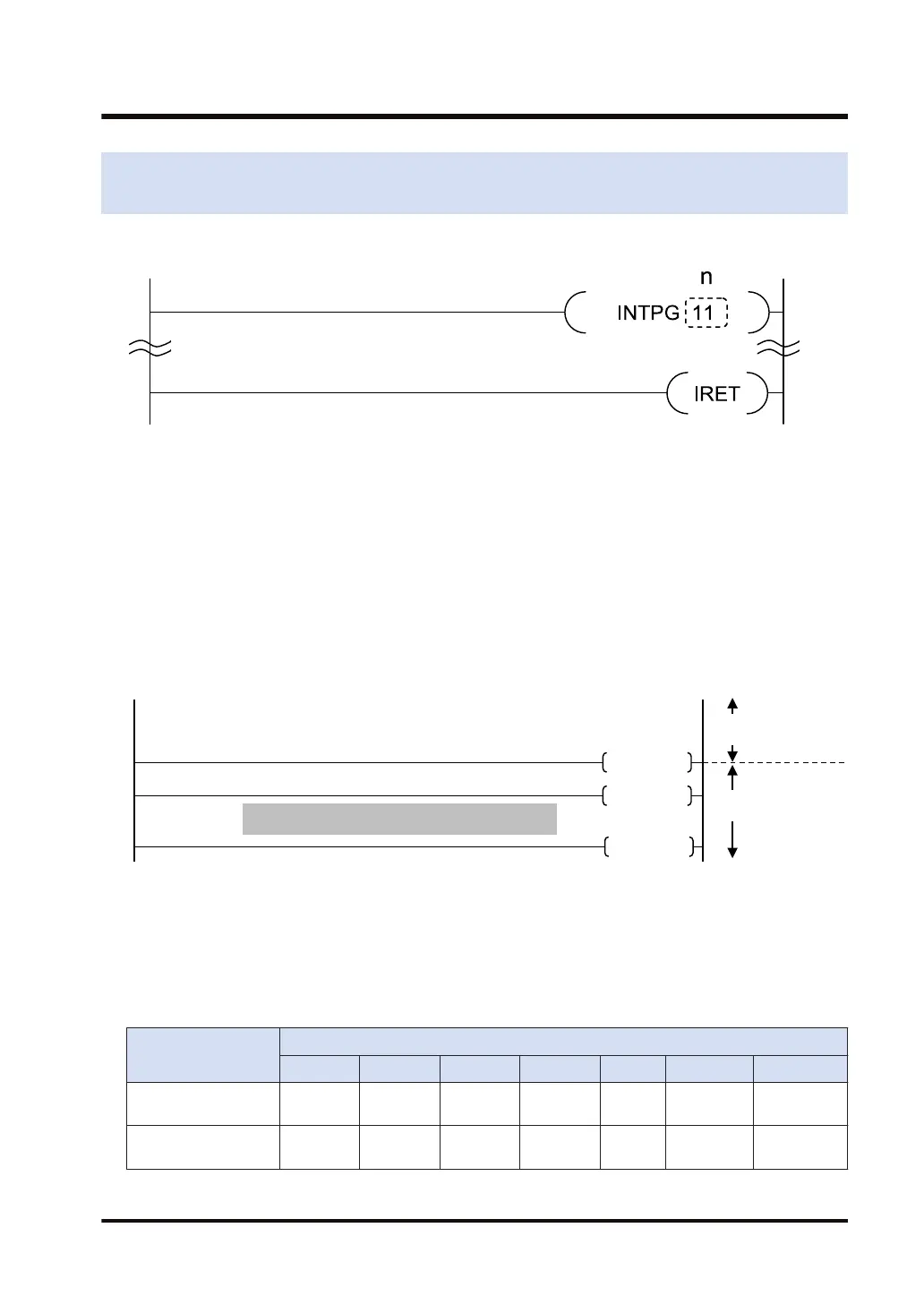
Outline of operation
● These instructions are described in subprogram areas in the same PB to indicate the start
and end positions of interruption program.
● Activates the interruption program of a corresponding program number when the unit's
interruption condition is met.
● Returns to the main program by executing the IRET instruction.
● To execute an interruption program, it is necessary to interrupt the CPU by the EI instruction
and enable a unit to interrupt by the IMASK instruction.
● The interruption activation request signal on the unit side will be held until the corresponding
interruption program is executed or the unit interruption clear instruction "ICLR" instruction is
executed.
Interrupt program
INTPG10
IRET
ED
Main program area
Sub program area
■
Specification of interruption program number [n]
● Interruption program number n is specified in decimal by the combination of a slot number (1
to 16) and a bit number (0 to 7).
● The allocation of the last one digit varies depending on units.
● The interruption program numbers for a high-speed counter unit and multiple input/output
unit are as shown below.
Comparison match
flag of unit
Corresponding interruption program No.
Slot 1 Slot 2 Slot 3 ----- ----- Slot 15 Slot 16
CH0 Comparison
match 0 flag
INTPG 10 INTPG 20 INTPG 30 ----- ----- INTPG 150 INTPG 160
CH0 Comparison
match 1 flag
INTPG 11 INTPG 21 INTPG 31 ----- ----- INTPG 151 INTPG 161
3.39 INTPG (Unit Interruption Program Start), IRET (Unit Interruption Program
End)
WUME-FP7CPUPGR-12 3-117

 Loading...


