15.9 PMGET (Acquiring SCU Parameters)
■
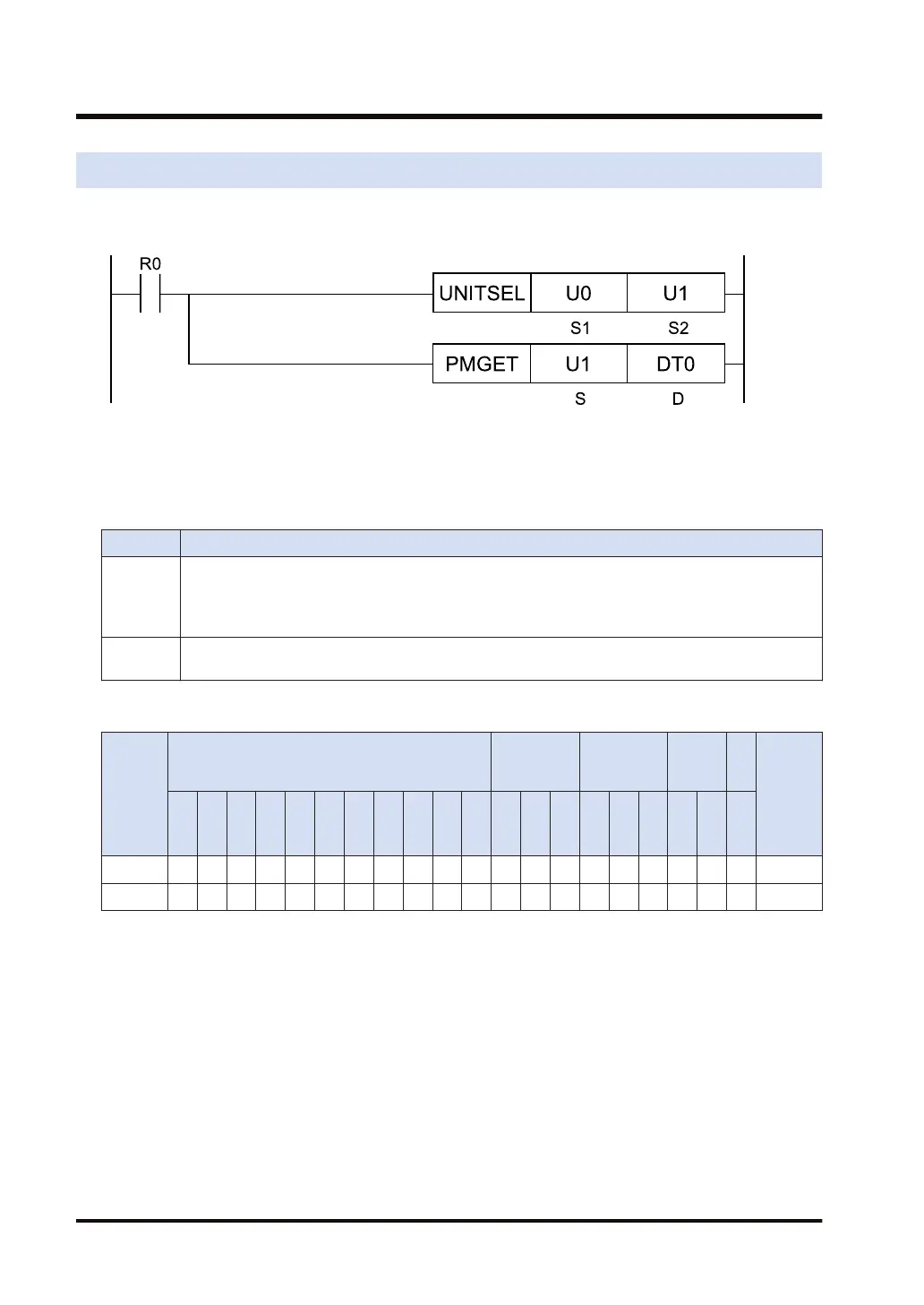
Ladder diagram
(Note 1) The above figure shows the case that S1=U0 (CPU unit with built-in SCU) and S2=U1 (port number 1)
are specified by the UNITSEL instruction.
■
List of operands
Operand Description
S
Type of acquired data
0: Communication parameters; 1: Communication monitoring area information; 2: PLC link status
flag information; 3: PLC link error frequency information; 4: PLC link time interval information; 5:
PLC link settings parameter monitoring information
D
Starting address of the area that stores the acquired communication parameter (monitor
information)
■
Available devices (●: Available)
Operan
d
16-Bit device:
32-Bit
device:
Integer
Real
numbe
r
St
rin
g
Index
modifie
r
W
X
W
Y
W
R
W
L
W
S
S
D
D
T
L
D
U
M
WI
W
O
TS
C
S
TE
C
E
IX K U H SF
D
F
" "
S ● ● ● ● ● ● ● ●
D ● ● ● ● ● ● ●
■
Outline of operation
● This instruction reads the parameters of the COM port of the unit, and stores them in the
area starting with [D].
● Specify the type of acquired data in [S].
■
Precautions for programming
● Describe the UNITSEL instruction immediately before the PMGET instruction, and specify
the slot and COM port numbers of the unit for which the parameters are acquired.
● The size of the area storing data varies in the range of 7 to 192 words according to the data
type specified in [S].
15.9 PMGET (Acquiring SCU Parameters)
15-58 WUME-FP7CPUPGR-12

 Loading...


