17.31 EIPMBODY (EIP Message Body Setting)
■
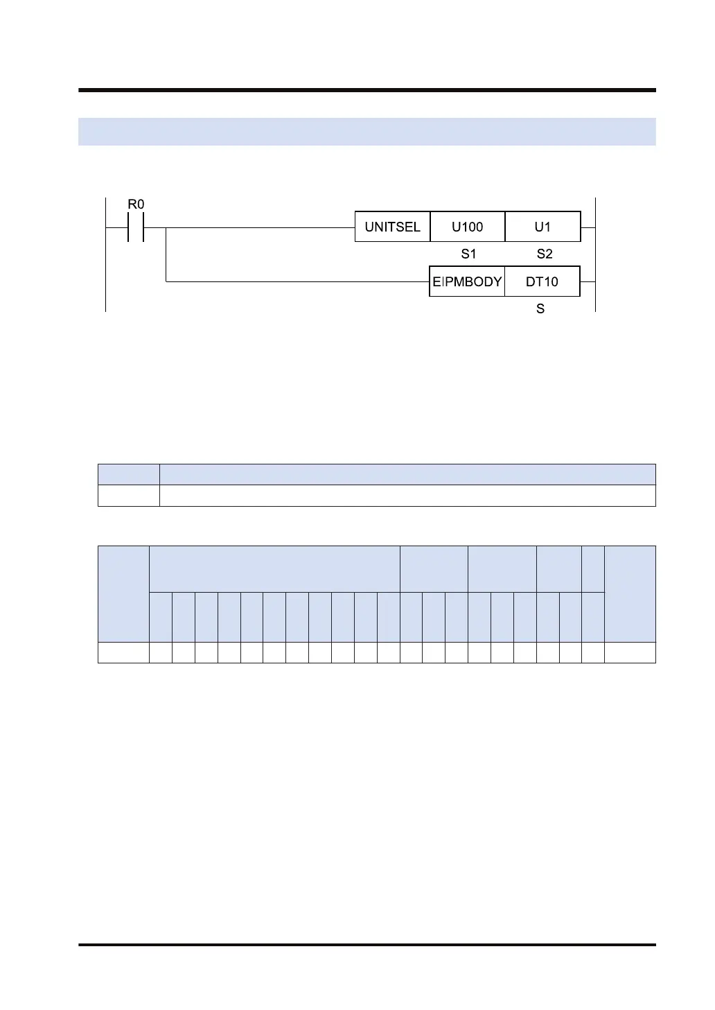
Ladder diagram
(Note 1) The above figure shows the case that S1=U100 (built-in ET-LAN in the CPU unit) and S2=U1
(connection number 1) are specified by the UNITSEL instruction.
■
Available operation units
No operation unit.
■
List of operands
Operand Description
S Specify the starting device number that stores the message body.
■
Devices that can be specified (indicated by ●)
Operan
d
16-Bit device:
32-Bit
device:
Integer
Real
numbe
r
St
rin
g
Index
modifie
r
W
X
W
Y
W
R
W
L
W
S
S
D
D
T
L
D
U
M
WI
W
O
TS
C
S
TE
C
E
IX K U H SF
D
F
" "
S ● ● ● ● ● ● ●
■
Outline of operation
● This instruction specifies the Ethernet unit to be targeted by the UNITSEL instruction.
● It sets the message body data of EIPMSEND instruction in the send buffer.
● The EIPMBODY instruction is used in combination with the EIPMSATT and EIPMSEND
instruction.
● When this instruction is called while message communication is being performed, no
operation is performed.
17.31 EIPMBODY (EIP Message Body Setting)
WUME-FP7CPUPGR-12 17-155

 Loading...


