2.4 Specification of Device Numbers
■
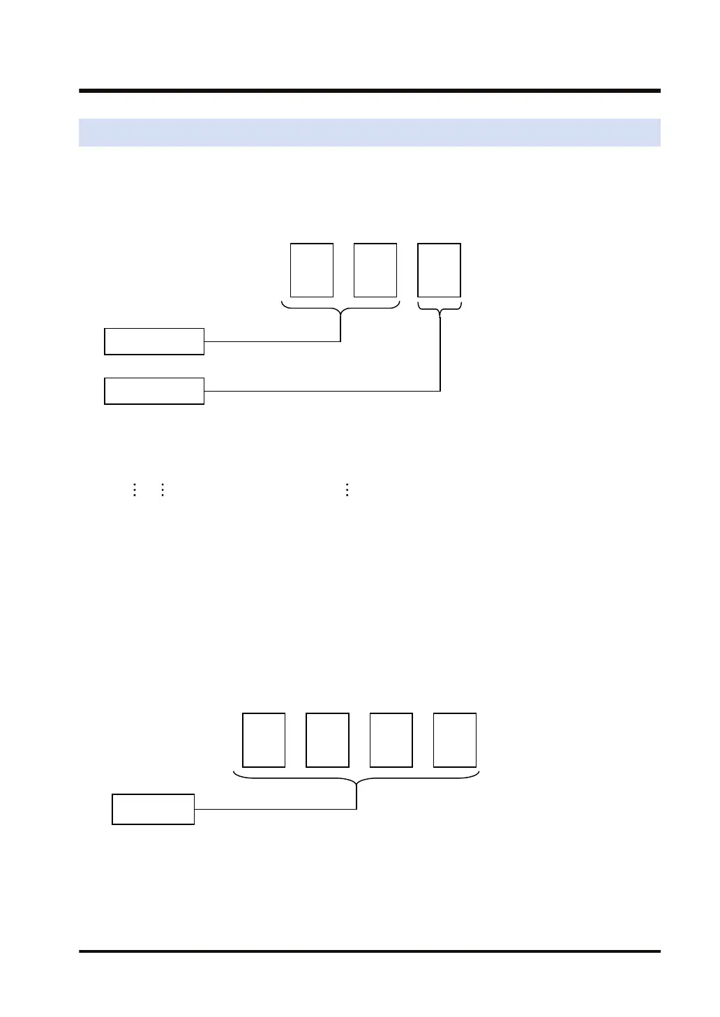
For external input (X), external output (Y), internal relay (R), link relay (L), pulse
relay (P), system relay (SR), direct input (IN), direct output (OT)
Since relays may be handled in units of 16 points, their numbers should be expressed as a
combination of decimal and hexadecimal numbers.
Decimal
Hexadecimal
1,2,3…
0,1,2…9,A,B…F
<Example> External input X
X 0, X 1,
・・・・・・・・・・・・・・・・・・・・・・・・・・
X F
X10, X11,
・・・・・・・・・・・・・・・・・・・・・・・・・・
X1F
X20, X21,
・・・・・・・・・・・・・・・・・・・・・・・・・・
X2F
■
Relay number of external input/output
● Only what is actually allocated to the input contact can be used for external input (X).
● Only what is actually allocated to the output contact can be output for external output (Y).
External outputs (Y) that are not allocated can be used as internal relays.
● Allocation of numbers is decided according to the combination of units.
■
Timer contact (T), counter contact (C), and error alarm relay (E)
● The numbers of timer/counter contacts correspond to the numbers of timers/counters, and
should be specified by decimal numbers.
● The numbers of error alarm relays should be specified by decimal numbers.
Decimal
0, 1, 2…
T 0,T 1 ・・・・・・・・・・・・・・・・・・・・・・・・・・T4095
C 0,C 1 ・・・・・・・・・・・・・・・・・・・・・・・・・・C1023
E0, E1 ・・・・・・・・・・・・・・・・・・・・・・・・・・ E4095
2.4 Specification of Device Numbers
WUME-FP7CPUPGR-12 2-15

 Loading...


