■
Types of system data registers (SD)
Classification Function
Environment settings,
operation status
The operation statuses of the PLC specified with the configuration data and the various
types of instructions are stored.
Example) Scan time
Description of error
Information such as information of a unit in which an abnormality occurred is stored.
Example) Self-diagnostic error code, slot number of the unit in which the abnormality
occurred, the address where the operation error occurred
Calendar timer
The year, month, day, hour, minute, second, and day of the week tracked by the
calendar timer are stored here.
2.6.7 WX, WY, WR, WL
■
How WX, WY, WR, WL works
● Relays (X, Y, R, L) can be handled as blocks of 16 points.
● Pulse relays (P) and error alarm relays (E) cannot be handled in word units.
● These are one-word (16-bit) memory areas, thus they can be treated as data memory.
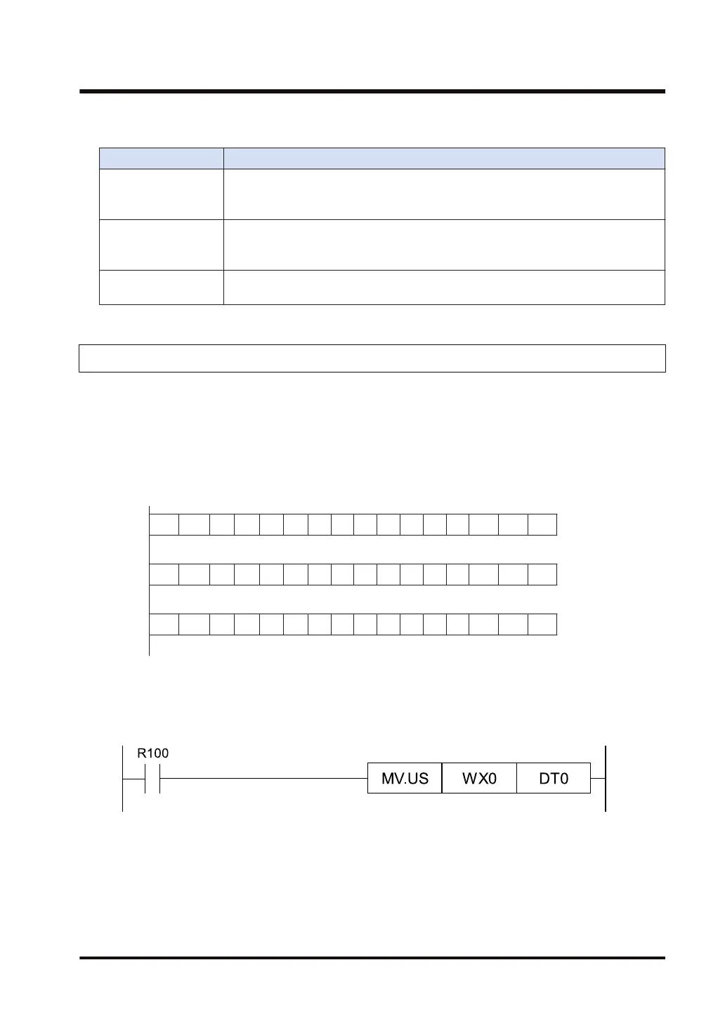
● The composition of the word-unit memory areas is shown below. Each element has a
corresponding number, as shown below.
WR0
RF RE RD RC RB RA R9 R8 R7 R6 R5 R4 R3 R2 R1 R0
WR1
R1F R1E • • • • • • • • • • • R12 R11 R10
WR2
R2F R2E • • • • • • • • • • • R22 R21 R20
■
WX, WY, WR, WL usage example
● WX and WY can be used for reading the input from intelligent units and for the external input/
output in word units.
●
WR can also be used as a shift register.
2.6 Description of the memory area
WUME-FP7CPUPGR-12 2-31

 Loading...


