2.6.2 DT*.n Data register (bit specification)
■
How bit specification of data register (DT*.n) works
● For the data register, specific bits of word data (16-bit data) can be extracted and used as bit
data by using bit specification.
Examples of usable instructions
ST, ST/, ST↑, ST↓, AN, AN/, AN↑, AN↓, OR, OR/, OR↑, OR↓, OT, KP, SET, RST, ALT, SEND,
RECV, PMSET
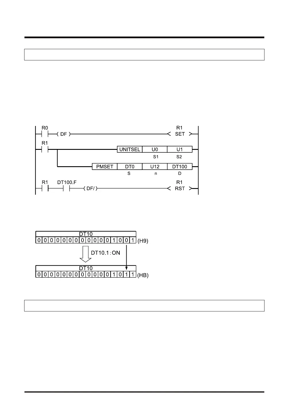
Example of program in which the F bit of DT100 is extracted and used as bit data
■
Precautions for use
● If the ON/OFF status changes for any of the bit data of the data register (DT*.n), the value of
the data register (DT) also changes.
2.6.3 LD Link register
■
How link register (LD) works
● Link register is data memory for when control units are connected in a network, as a "PLC
link" data memory for shared use between control units.
● When data is written to the link register of a PLC, the same contents are stored in link
registers with the same number for other PLC connected in the network.
● You can send and receive data between PLCs in this manner when using link registers.
2.6 Description of the memory area
2-28 WUME-FP7CPUPGR-12

 Loading...


