8.3 BSR (Right Shift for n Digits)
■
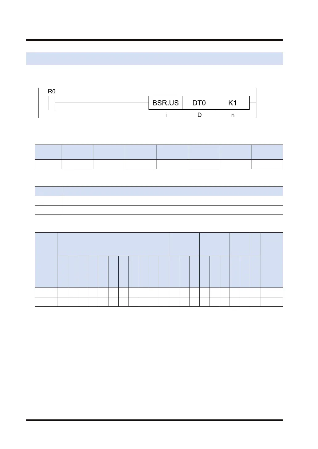
Ladder diagram
■
Available operation units (●: Available)
Operatio
n unit
bit US SS UL SL SF DF
i ● ● ● ●
■
List of operands
Operand Description
D The device address where the data to be shifted is stored
n The device address where the number of shift digits is stored, or the constant
■
Available devices (●: Available)
Operan
d
16-Bit device:
32-Bit
device:
(Note 1)
Integer
Real
numbe
r
St
rin
g
Index
modifie
r
(Note 2)
W
X
W
Y
W
R
W
L
W
S
S
D
D
T
L
D
U
M
WI
W
O
TS
C
S
TE
C
E
IX
(N
ote
3)
K
(N
ote
4)
U
(N
ote
5)
H SF
D
F
" "
D ● ● ● ● ● ● ● ● ● ● ● ●
n ● ● ● ● ● ● ● ● ● ● ● ● ● ● ● ●
(Note 1) Cannot be specified when the operation unit is 16-bit integer (SS, US).
(Note 2) Only 16-bit devices, 32-bit devices, and integer constants can be modified. (Real number constants,
and character constants cannot be specified.)
(Note 3) Index register (I0 to IE)
(Note 4) Can be specified only when the operation unit is signed integer (SS, SL).
(Note 5) Can be specified only when the operation unit is unsigned integer (US, UL).
■
Outline of operation
● This instruction shifts the data specified by [D] to the right (to the low bit position) for [n] digits
(4 bits) (specified in decimal).
● Once the data is shifted, [n] digits are filled with 0 from the highest bit before shifting the
data.
● Only the lower 8 bits in data are available for [n].
8.3 BSR (Right Shift for n Digits)
8-6 WUME-FP7CPUPGR-12

 Loading...


