19.2 Clock and Time Data
■
Built-in calendar timer of the CPU unit
● The calendar timer should be adjusted in the Set PLC Date and Time menu of the tool
software FPWIN GR7, or using the TIMEWT instruction.
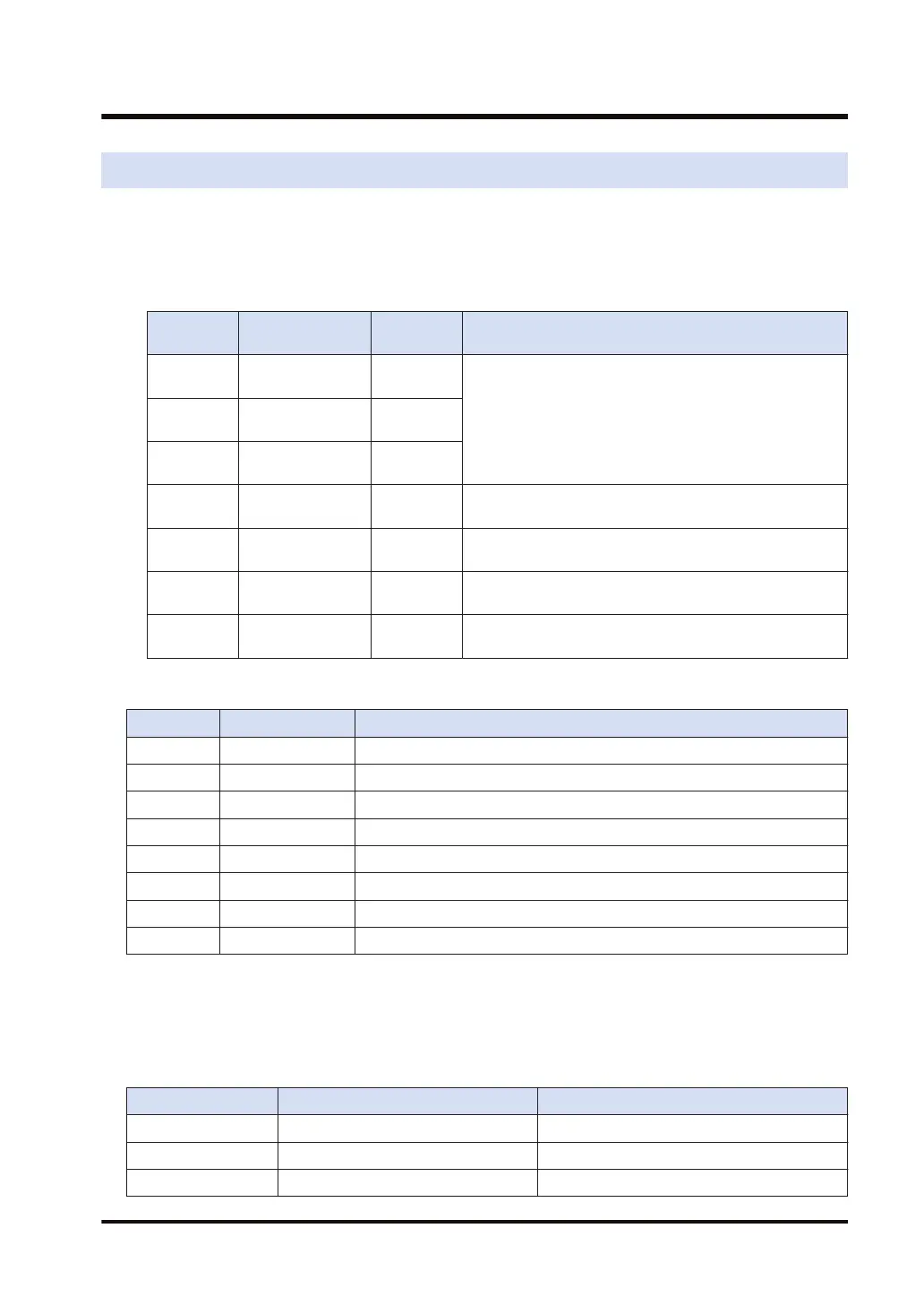
● The set values are stored in the system data registers SD50 through 56, as listed below.
Device No.
Name of
instruction
Data range
Remarks
SD50
Calendar timer
(year)
00 to 99
The two lower digits of year in A.D. can be adjusted (up to
2099). Leap years can be set in this operation. Take leap
years into account during setting. A year that can be
divided by 4 is a leap year, and the days of February can
be set to 29.
SD51
Calendar timer
(month)
01 to 12
SD52
Calendar timer
(day)
01 to 31
SD53
Calendar timer
(hours)
0 to 23
SD54
Calendar timer
(minutes)
0 to 59
SD55
Calendar timer
(seconds)
0 to 59
SD56
Calendar timer
(day-of-the-week)
0 to 6
0: Sun., 1: Mon., 2: Tue., 3: Wed., 4: Thu., 5: Fri., 6: Sat.
■
Instructions that handle clock or time data
Mnemonic Operand Function
HMSS S, D (Time data) → (Seconds data)
SHMS S, D (Seconds data) → (Time data)
CADD S1,S2,D (Clock data) + (Time data) → (Clock data)
CSUB S1,S2,D (Clock data) - (Time data) → (Clock data)
TMSEC S, D (Clock data) → (Seconds data from the base time)
SECTM S, D (Seconds data from the base time) → (Clock data)
TIMEWT S (Clock data) → (SD50 to SD56)
SUMMER S1,S2, S3,D (Clock data) → (Clock data)
■
Format of clock data
One-word 16-bit binary data are allocated to each unit (year, month, day, hours, minutes and
seconds), and the overall clock data are handled in the unit of 6 words.
Example) DT0 is specified for operand
Word Range:
DT0 Year 00 to 99
DT1 Month 01 to 12
DT2 Day 01 to 31
19.2 Clock and Time Data
WUME-FP7CPUPGR-12 19-3

 Loading...


