17.24 SMTPcSET (Mail Transmission Setting)
■
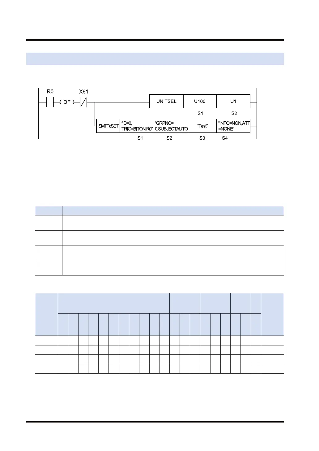
Ladder diagram
(Note 1) The above figure shows the case that S1=U100 (built-in ET-LAN in the CPU unit) and S2=U1
(connection number 1) are specified by the UNITSEL instruction. Set a desired value for [S2].
(Note 2) By copying and pasting the following text in the instruction list box of FPWIN GR7, the operand part of
the above program can be input.
SMTPcSET "ID=0,TRIG=BITON,R0" "GRPNO=0,SUBJECTAUTO" "Test" "INFO=NON,ATT=NONE"
■
List of operands
Operand Description
S1
Starting address of the device area that stores the string data that indicates a setting number and a
send trigger, or a character constant
S2
Starting address of the device area that stores the string data that indicates the destination group
number and the subject of the mail to be sent, or a character constant.
S3
Starting address of the device area that stores the string data that indicates the text of the mail to
be sent, or a character constant.
S4
Starting address of the device area that stores the string data that indicates the attached data
specification of the mail to be sent, or a character constant.
■
Devices that can be specified (indicated by ●)
Operan
d
16-Bit device:
32-Bit
device:
Integer
Real
numbe
r
St
rin
g
Index
modifie
r
W
X
W
Y
W
R
W
L
W
S
S
D
D
T
L
D
U
M
WI
W
O
TS
C
S
TE
C
E
IX K U H SF
D
F
" "
S1 ● ● ● ● ● ● ●
S2 ● ● ● ● ● ● ●
S3 ● ● ● ● ● ● ●
S4 ● ● ● ● ● ● ●
■
Outline of operation
● This instruction configures the mail transmission settings.
● Before executing this instruction, use the "17.23 SMTPcADD (Destination Group Setting)"
instruction or the programming tool software "FPWIN GR7" to configure event mail settings.
17.24 SMTPcSET (Mail Transmission Setting)
17-120 WUME-FP7CPUPGR-12

 Loading...


