3.4 ST↑, ST↓ (Leading and Trailing Contact Instructions)
■
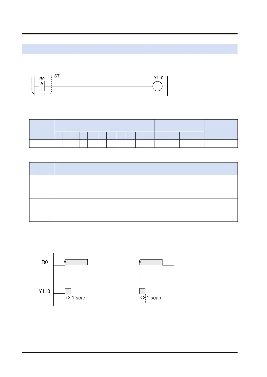
Ladder diagram
■
Devices that can be specified (indicated by ●)
Operand
Bit device
Specification of bit of
word device
Index modifier
X Y R L T C P E SR IN OT DT.n LD.n
bit ● ● ● ● ● ● ● ● ● ● ● ● ●
■
Outline of operation
Type of
instruction
Operation
ST↑
Conduction takes place for 1 scan only following the change of a signal from the OFF to ON state
(rise).
Begins a logic operation by treating the input contact as a Form A (normally open) or Form B
(normally closed).
ST↓
Conduction takes place for 1 scan only following the change of a signal from the ON to OFF state
(fall).
Begins a logic operation by treating the input contact as a Form A (normally open) or Form B
(normally closed).
■
Operation Example
Program operation of "ST↑" in the ladder diagram
When R0 changes from OFF to ON (rise), only 1 scan is output to Y110.
3.4 ST↑, ST↓ (Leading and Trailing Contact Instructions)
3-8 WUME-FP7CPUPGR-12

 Loading...


