8.6 BITL (Left Shift of Multiple Devices for n Bits)
■
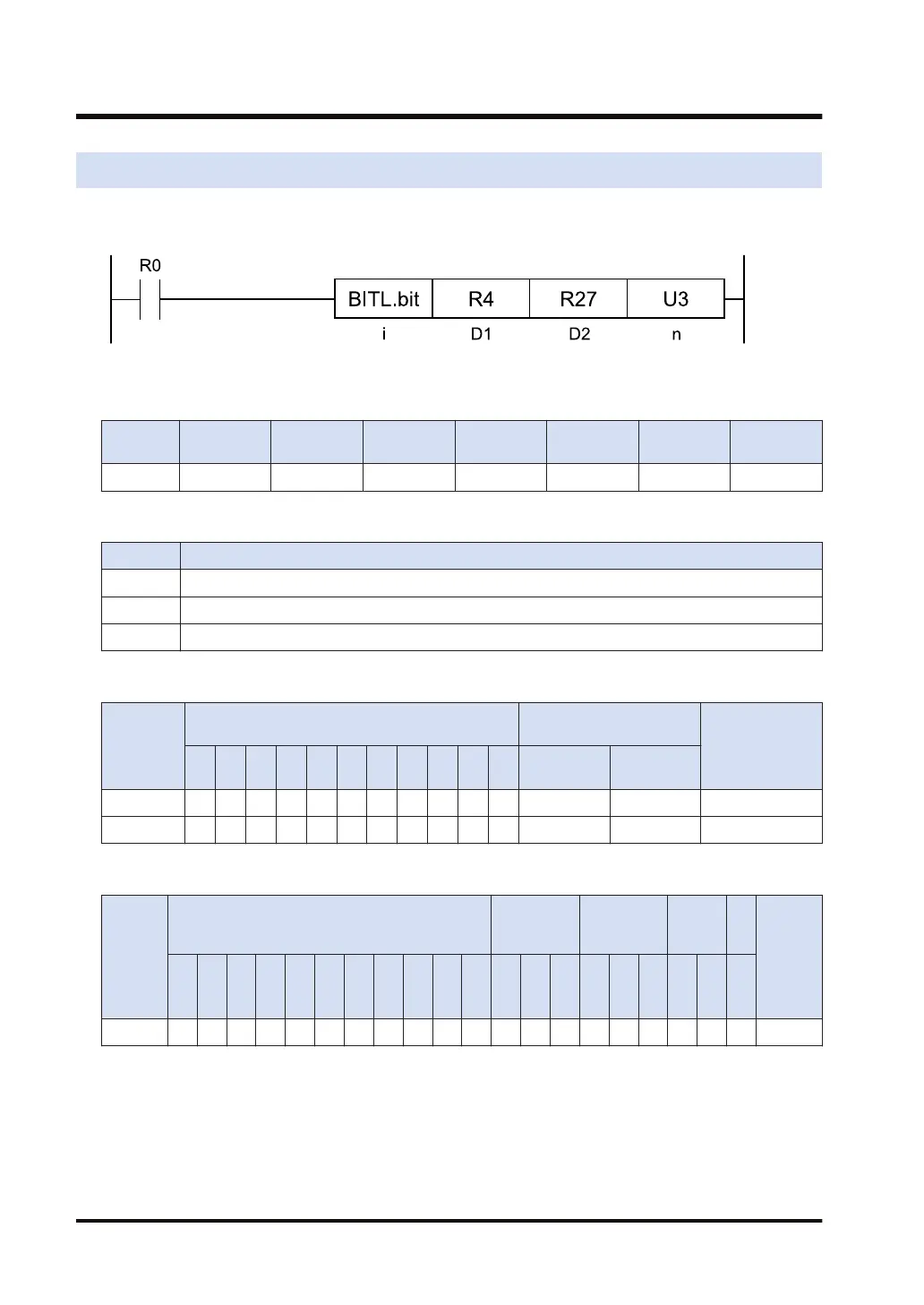
Ladder diagram
■
Available operation units (●: Available)
Operatio
n unit
bit US SS UL SL SF DF
i ●
■
List of operands
Operand Description
D1 Starting address of the devices to be shifted (data format: according to the operation unit)
D2 End address of the devices to be shifted (data format: according to the operation unit)
n The device address where the number of shift bits is stored, or the constant
■
Available bit devices (●: Available)
Operand
Bit device
Specification of bit of
word device
Index modifier
X Y R L T C P E
S
R
IN
O
T
DT.n LD.n
D1 ● ● ● ● ● ● ● ●
D2 ● ● ● ● ● ● ● ●
■
Available word devices (●: Available)
Operan
d
16-Bit device:
32-Bit
device:
Integer
Real
numbe
r
St
rin
g
Index
modifie
r
(Note 1)
W
X
W
Y
W
R
W
L
W
S
S
D
D
T
L
D
U
M
WI
W
O
TS
C
S
TE
C
E
IX K U H SF
D
F
" "
n ● ● ● ● ● ● ● ● ● ● ● ●
(Note 1) Only 16-bit devices, 32-bit devices, and integer constants can be modified. (Real number constants,
and character constants cannot be specified.)
■
Outline of operation
● This instruction shifts the range from [D1] to [D2] to the left by [n] bits.
● The starting address of the bit is specified by [D1], and the end address by [D2].
8.6 BITL (Left Shift of Multiple Devices for n Bits)
8-12 WUME-FP7CPUPGR-12

 Loading...


