9.3 BTI (Bit Inversion)
■
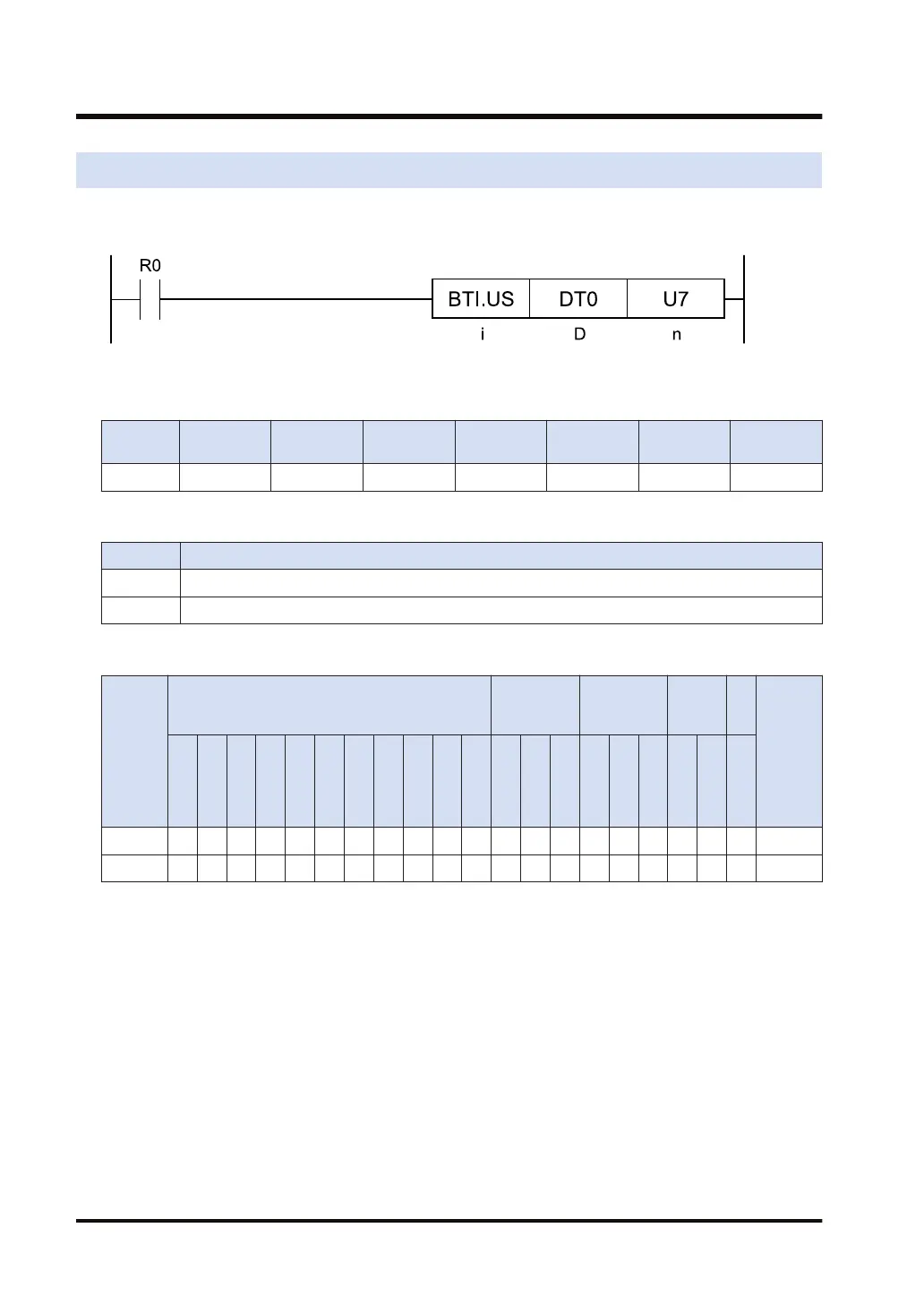
Ladder diagram
■
Available operation units (●: Available)
Operatio
n unit
bit US SS UL SL SF DF
i ●
■
List of operands
Operand Description
D Inversion target data (device address)
n Bit number (device address or constant) (available data range: 0 to 15)
■
Available devices (●: Available)
Operan
d
16-Bit device:
32-Bit
device:
Integer
Real
numbe
r
St
rin
g
Index
modifie
r
(Note 1)
W
X
W
Y
W
R
W
L
W
S
S
D
D
T
L
D
U
M
WI
W
O
TS
C
S
TE
C
E
IX
(N
ote
2)
K U H SF
D
F
" "
S ● ● ●
D ● ● ● ● ● ● ● ● ●
(Note 1) Only 16-bit devices and integer constants can be modified.
(Note 2) Index register (I0 to IE)
■
Outline of operation
● This instruction inverts the [n]th bit in the area specified by [D] according to the operation unit
of [i].
9.3 BTI (Bit Inversion)
9-6 WUME-FP7CPUPGR-12

 Loading...


