6.16 AND (Logical Conjunction)
■
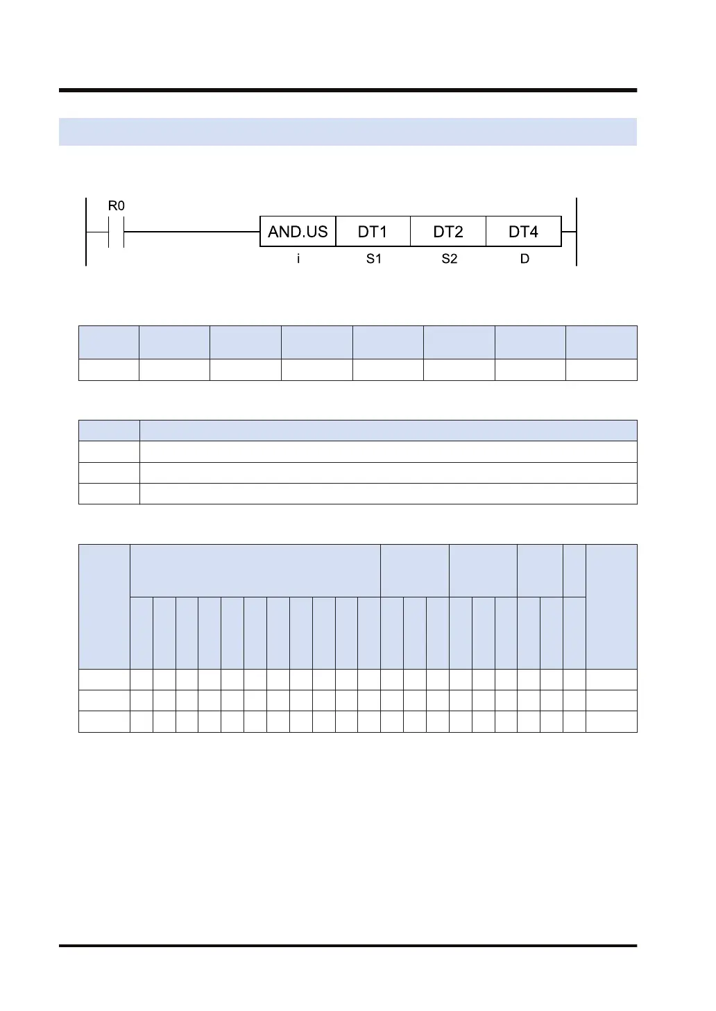
Ladder diagram
■
Available operation units (●: Available)
Operatio
n unit
bit US SS UL SL SF DF
i ● ● ● ●
■
List of operands
Operand Description
S1 Calculation target data 1 (device address or constant)
S2 Calculation target data 2 (device address or constant)
D Calculation result data (device address)
■
Available devices (●: Available)
Operan
d
16-Bit device:
32-Bit
device:
(Note 1)
Integer
Real
numbe
r
St
rin
g
Index
modifie
r
W
X
W
Y
W
R
W
L
W
S
S
D
D
T
L
D
U
M
WI
W
O
TS
C
S
TE
C
E
IX
(N
ote
2)
K
(N
ote
3)
U
(N
ote
4)
H SF
D
F
" "
S1 ● ● ● ● ● ● ● ● ● ● ● ● ● ● ● ● ● ●
S2 ● ● ● ● ● ● ● ● ● ● ● ● ● ● ● ● ● ●
D ● ● ● ● ● ● ● ● ● ● ● ●
(Note 1) Cannot be specified when the operation unit is 16-bit integer (SS, US).
(Note 2) Index register (I0 to IE)
(Note 3) Can be specified only when the operation unit is signed integer (SS, SL).
(Note 4) Can be specified only when the operation unit is unsigned integer (US, UL).
■
Outline of operation
● This instruction calculates the logical conjunction for [S1] and [S2] by the operation unit [i].
● The calculation result is stored in the address starting with [D].
[S1] ˄ [S2] →[D]
6.16 AND (Logical Conjunction)
6-34 WUME-FP7CPUPGR-12

 Loading...


