8.15 CMPR (Data Table Shift-Out and Compress)
■
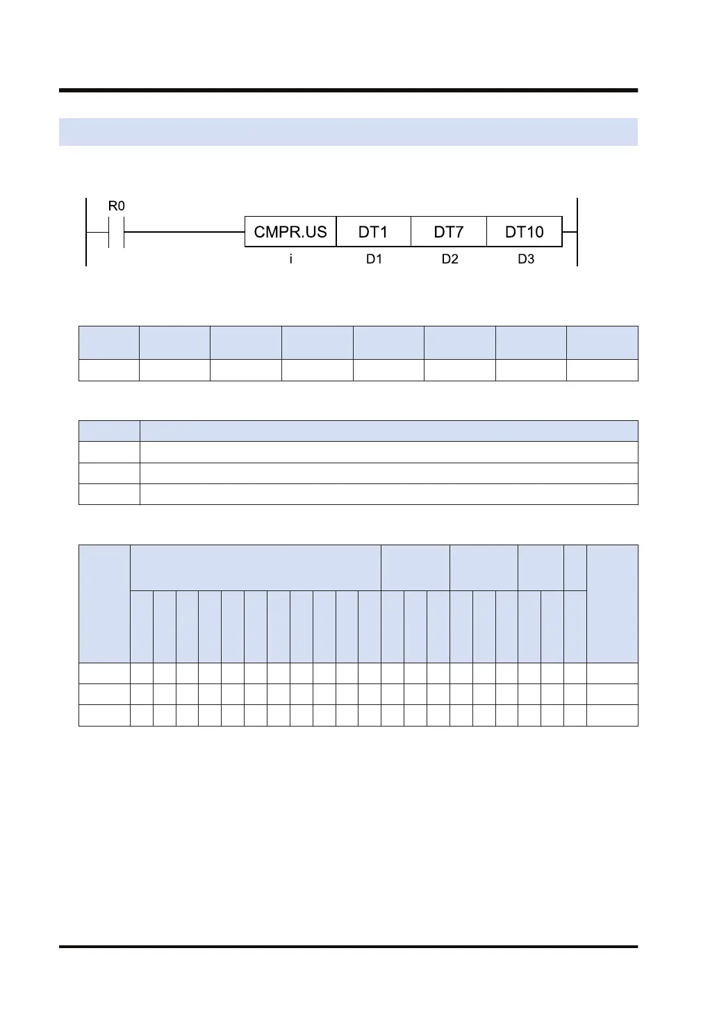
Ladder diagram
■
Available operation units (●: Available)
Operatio
n unit
bit US SS UL SL SF DF
i ● ●
■
List of operands
Operand Description
D1 Starting address of the buffer
D2 End address of the buffer
D3 Device address to store the read data
■
Available devices (●: Available)
Operan
d
16-Bit device:
32-Bit
device:
Integer
Real
numbe
r
St
rin
g
Index
modifie
r
W
X
W
Y
W
R
W
L
W
S
S
D
D
T
L
D
U
M
WI
W
O
TS
C
S
TE
C
E
IX
(N
ote
1)
K U H SF
D
F
" "
D1 ● ● ● ● ● ● ● ● ●
D2 ● ● ● ● ● ● ● ● ●
D3 ● ● ● ● ● ● ● ● ●
(Note 1) Index register (I0 to IE)
■
Outline of operation
● According to the operation unit [i], the instruction transfers [D2] to [D3], and compresses the
areas specified by [D1] to [D2].
(Except the data transferred to [D3] at the time of compression)
● The data in the specified area, excluding 0, are allocated in descending order from the higher
address of the specified area, and the remaining area is cleared to zero.
8.15 CMPR (Data Table Shift-Out and Compress)
8-30 WUME-FP7CPUPGR-12

 Loading...


