13.12 POSSET (Setting of Positioning Starting Table)
■
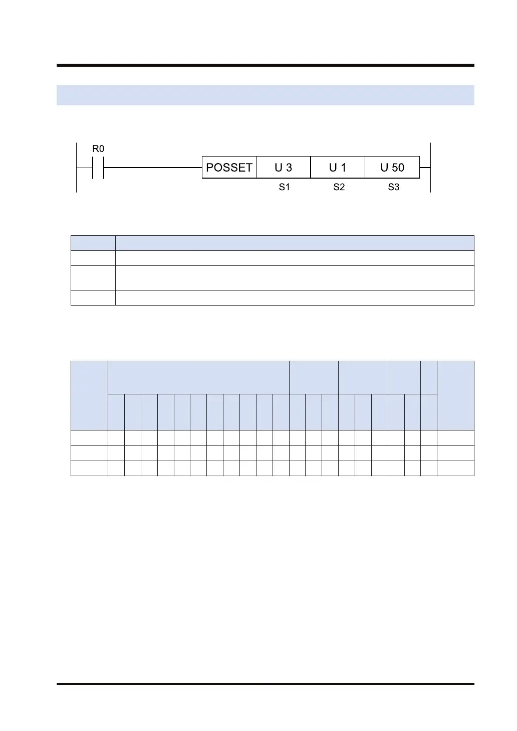
Ladder diagram
■
List of operands
Operand Description
S1 Slot number where the positioning unit is attached (unsigned 16-bit integer)
S2
Axis number to start up the positioning table (unsigned 16-bit integer); 1 to 4: Axis 1 to 4; 8: Virtual
axis
S3 Table number to start up the position control (unsigned 16-bit integer); 1 to 600, 10001 to 10100
(Note 1) If a value out of the available range is set as the starting table number, the positioning unit gives an
error notification.
■
Available devices (●: Available)
Operan
d
16-Bit device:
32-Bit
device:
Integer
Real
numbe
r
St
rin
g
Index
modifie
r
W
X
W
Y
W
R
W
L
W
S
S
D
D
T
L
D
U
M
WI
W
O
TS
C
S
TE
C
E
IX K U H SF
D
F
" "
S1 ● ● ● ● ● ● ● ● ● ● ● ●
S2 ● ● ● ● ● ● ● ● ● ● ● ●
S3 ● ● ● ● ● ● ● ● ● ● ● ●
■
Outline of operation
● It is described right before the program which starts positioning and the positioning data table
to be started is set.
● For the axis number of the positioning units specified by [S1] and [S2], the data table
specified by [S3] is set.
● Data for the positioning data table should be set using Configurator PM7 in the tool software
FPWIN GR7, or a user program.
● Positioning parameters should be set in the configuration menu of the tool software FPWIN
GR7.
13.12 POSSET (Setting of Positioning Starting Table)
WUME-FP7CPUPGR-12 13-19

 Loading...


