16.6 PMSET / pPMSET (Change of MEWNET-W Parameters)
■
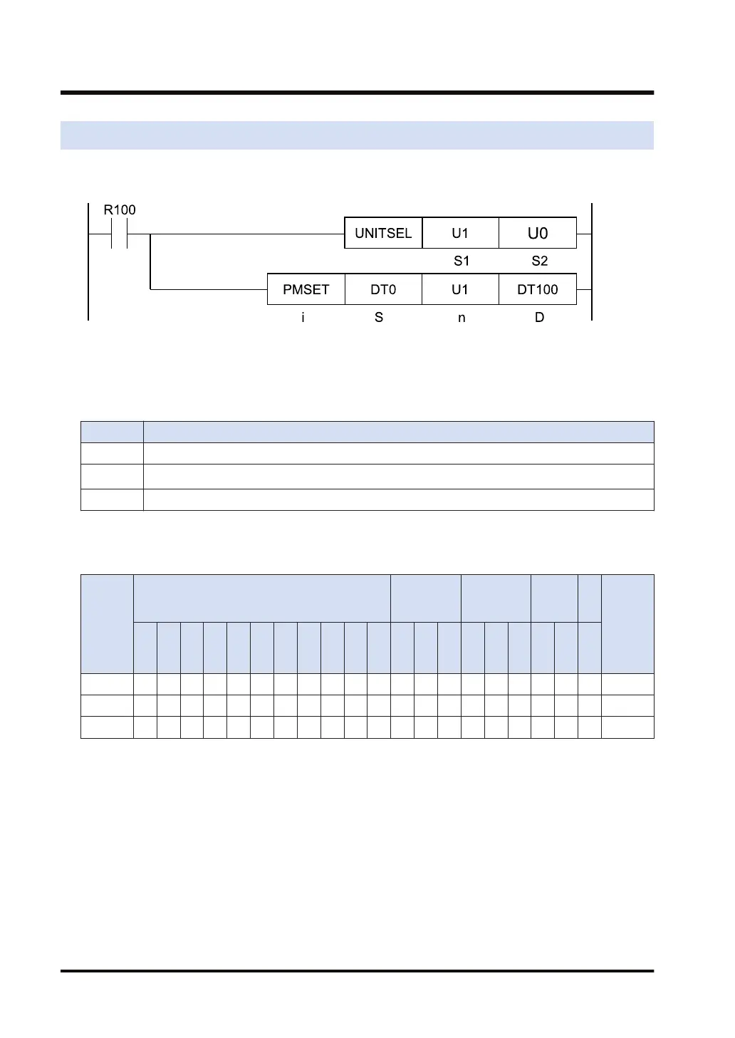
Ladder diagram
(Note 1) The above figure shows the case that the FP7 multi-wire link unit for S1=U1 (slot number 1) is
specified by the UNITSEL instruction.
■
List of operands
Operand Description
S Start of the area that stores data to be set as communication parameters
n
Specified number of words (Setting range: 10 or 1)
(Note 1)
D Starting address of the device area in the master unit that stores the processing result (1 word)
(Note 1) When the station number is 17 or more, specify 1.
■
Available devices (●: Available)
Operan
d
16-Bit device:
32-Bit
device:
Integer
Real
numbe
r
St
rin
g
Index
modifie
r
W
X
W
Y
W
R
W
L
W
S
S
D
D
T
L
D
U
M
WI
W
O
TS
C
S
TE
C
E
IX K U H SF
D
F
" "
S ● ● ● ● ● ● ●
n ● ● ● ● ● ● ● ●
D ● ● ● ● ● ● ●
■
Outline of operation
● The MEWNET-W communication parameters of the FP7 multi-wire link unit are changed with
a user program.
● Set communication parameters to be changed within [n] words from the area starting with
[S], and execute the PMSET/pPMSET instruction, to issue the setting change request to the
unit.
● By reading setting parameters using the PMGET instruction, and setting parameters to be
changed using the PMSET/pPMSET instruction, the settings can be simplified.
16.6 PMSET / pPMSET (Change of MEWNET-W Parameters)
16-20 WUME-FP7CPUPGR-12

 Loading...


