16.1 SEND (When FP7 Multi-wire Link Unit Is Used)
■
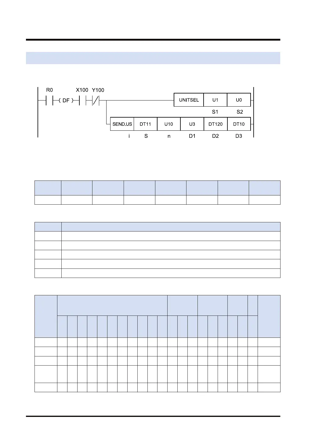
Ladder diagram
(Note 1) The above figure shows the case that the FP7 multi-wire link unit for S1=U1 (slot number 1) is
specified by the UNITSEL instruction.
■
Available operation units (●: Available)
Operatio
n unit
bit US SS UL SL SF DF
i ● ●
■
List of operands
Operand Description
S Starting address of the sender data area
n Amount of sent data
D1 Partner station number
D2 Starting address of the device in the receiver data area of the partner unit
D3 Starting address of the device area of the master unit that stores the execution result code (1 word)
■
Available word devices (●: Available)
Operan
d
16-Bit device:
32-Bit
device:
Integer
Real
numbe
r
St
rin
g
Index
modifie
r
W
X
W
Y
W
R
W
L
W
S
S
D
D
T
L
D
U
M
WI
W
O
TS
C
S
TE
C
E
IX K U H SF
D
F
" "
S ● ● ● ● ● ● ●
n ● ● ● ● ● ● ● ● ●
D1 ● ● ● ● ● ● ● ● ●
D2
(Note
1)
● ● ● ● ● ● ●
D3 ● ● ● ● ● ● ●
(Note 1) When the destination unit is FP7, only global devices can be specified. (Local devices cannot be
specified.)
16.1 SEND (When FP7 Multi-wire Link Unit Is Used)
16-2 WUME-FP7CPUPGR-12

 Loading...


