■
Operation of LRSR (left/right shift register)
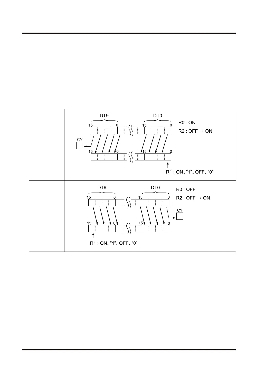
1. When the shift input changes from OFF to ON (the reset input is OFF), the contents of the
area specified by [D1] and [D2] are shifted one bit to the left or right.
2. When the data is shifted, 1 will be set in the empty bit left by the shift (the most significant
bit or least significant bit) if the data input is ON, and 0 if the data input is OFF. In addition,
the bit pushed out due to shifting (the most significant bit for left shift and the least
significant bit for right shift) is set in the system relay SR9 (carry flag).
3. If the reset input is ON, the contents of the specified area are cleared to 0.
■
Operation diagram
Left shift
Right shift
■
Precautions for programming
● The LRSR instruction detects rising from OFF to ON of the shift input and shifts the register
contents. If the shift input remains continuously ON, a shift will only take place at the rise. No
further shifts will take place.
● The register contents will not be shifted for the first scan if the shift input is already ON when
the operation mode is switched to RUN or the power is turned on in the RUN mode.
3.24 LRSR (Left/Right Shift Register)
3-74 WUME-FP7CPUPGR-12

 Loading...


