<Example> If R0 goes ON when an error occurs
K3
+1
No. of error alarm relays in the ON
state
Relay numbers of error alarm relays
in the ON state
K12
K5
K0
K0
SD60
SD61
SD62
SD63
SD64
K4
K21
K12
K5
K15
K21
SD65
K0
E15
SET
R0
・・・・
■
Reset program for a given error alarm relay
● The RST instruction should be used to turn OFF error alarm relays when an error has been
corrected.
<Example> If R0 goes ON when an error is corrected
-1
No. of error alarm relays in the ON state
Relay numbers of error alarm relays
in the ON state
X1:ON
K3
K12
K5
K0
K0
SD60
SD61
SD62
SD63
SD64
K21
SD65
K3
K5
K0
K0
K21
R0
E12
RST
・・・
■
Clearing all buffer areas
● To reset all error alarm relays, use RST instruction to specify the system data register SD60,
following the method shown below.
■
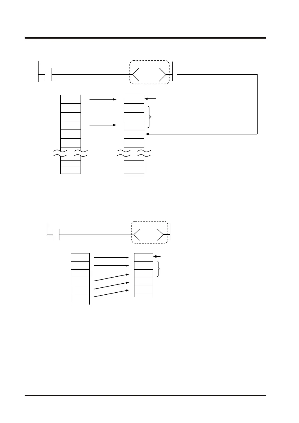
Clearing buffer areas and initial data
● Of the areas in which relay numbers are stored, only SD60 and SD61 can be cleared by
directly specifying the system data register with RST instruction.
● When SD60 is specified, all of the error information in the buffer is cleared, and when SD61
is specified, the relay number at the head of the buffer area is cleared, and the buffer is filled
as shown in the example below.
2.5 Explanations about Relays
2-24 WUME-FP7CPUPGR-12

 Loading...


