■
Outline of operation
Compares signed data specified in [S1] with signed data specified in [S2].
Begins a logic operation as a contact connected when the comparison result is in the specified
state (such as =, <, or >).
■
Comparison result and operation
Relationship between [S1] and [S2] [S1] < [S2] [S1] = [S2] [S1] > [S2]
Comparison instruction ST = OFF ON OFF
ST <> ON OFF ON
ST > OFF OFF ON
ST >= OFF ON ON
ST < ON OFF OFF
ST <= ON ON OFF
(Note 1) ● "< >" represents "≠".
● ">=" represents "≥".
● "<=" represents "≤".
■
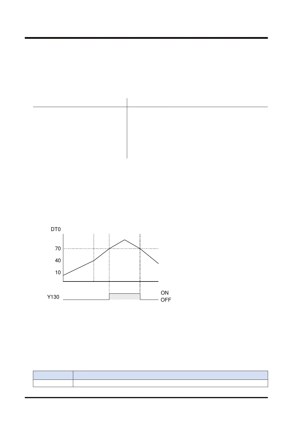
Operation Example
Program operation of "ST >=" in the ladder diagram
Compares the value of data register DT0 with K70. If DT0 = K70, external output Y130 turns
ON.
■
Precautions for use
● The "ST=", "ST<>", "ST>", "ST>=", "ST<", and "ST<=" instructions are initiated from the bus
bar.
● Since BCD data is assumed to be a negative value during comparison if the most significant
bit is 1, the comparison result may become incorrect. In such a case, use the BIN instruction
to convert the data into binary before comparison.
■
Flag operations
Name Description
SR7 ON if the specified address using the index modification exceeds a limit.
3.46 ST=, ST<>, ST>, ST>=, ST<, ST<= (Data Comparison: Start)
3-134 WUME-FP7CPUPGR-12

 Loading...


