■
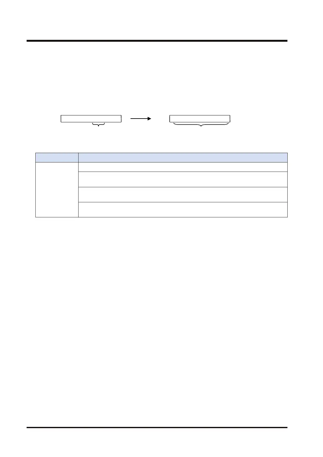
Processing
0000 0000 0111 0000
DT1
0000 0000 1000 0000
DT2
4 bits
15 4 0 15 7 0
16 bits
Example) Decode 4 bits from Bit 4
[S]…DT1
[n]…H 0404 [D]…DT2
* Store the result of decoding the specified portion (“0111 ”=7) into the 16-bit
(2
4
-bit) device address starting with DT2.
* The 16-bit area starting with DT2 turns ON, while the other bits become '0'.
■
Flag operations
Name Description
SR7
SR8
(ER)
To be set in the case of out-of-range in indirect access (index modification).
To be set when the conversion-enabled bit length "nL" is not in the following range: 1 ≤ nL ≤
8.
To be set when the sum of the conversion starting bit number (nH) and the conversion-
enabled bit length (nL) is not in the following range: 1 ≤ "nH + nL" ≤ 16.
To be set if, when the decoded result is stored in the device address specified by [D], it
exceeds the area.
7.7 DECO (Decoding)
7-16 WUME-FP7CPUPGR-12

 Loading...


