■
Outline of operation
● The data specified by [S1] are scaled according to the data table specified by [S2]. The result
is stored in the device area specified by [D].
■
Processing
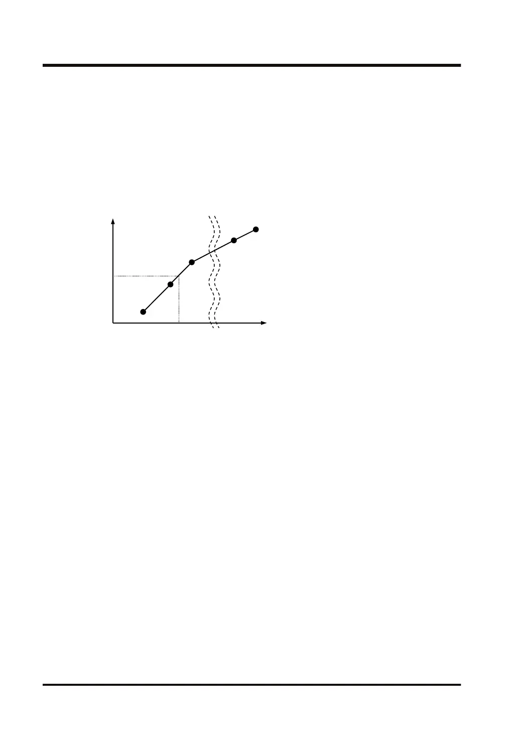
● Regardless of the operation unit, the output value Y for [D], corresponding to the input value
X for [S1], is calculated.
● In response to the information of input value X specified by [S1], the information of output
value Y is calculated according to the [S2] data table. The result is stored into the [D] area.
Output
value
Input
value
(x1, y1)
(x2, y2)
(x3, y3)
(xn-1, yn-1)
(xn, yn)
Y = [D]
X = [S1]
■
Structure of data table [S2]
● The number for data table "n" (setting range: 2 to 256) is determined by the value [n]
specified for the starting address of the data table [S2]. n is 16-bit data, regardless of the
operation unit.
● Scaling data (x1 to xn, y1 to yn) is stored from [S2]+1. Depending on the operation unit, the
data table occupies 16 bits (1 word), 32 bits (2 words), or 64 bits (4 words).
● The structure of data table [S2] that is used for scaling (linearization) is shown below.
10.7 SCAL (Linearization)
10-28 WUME-FP7CPUPGR-12

 Loading...


